Leaderboard

Popular Content
Showing content with the highest reputation since 02/09/2026 in all areas
-
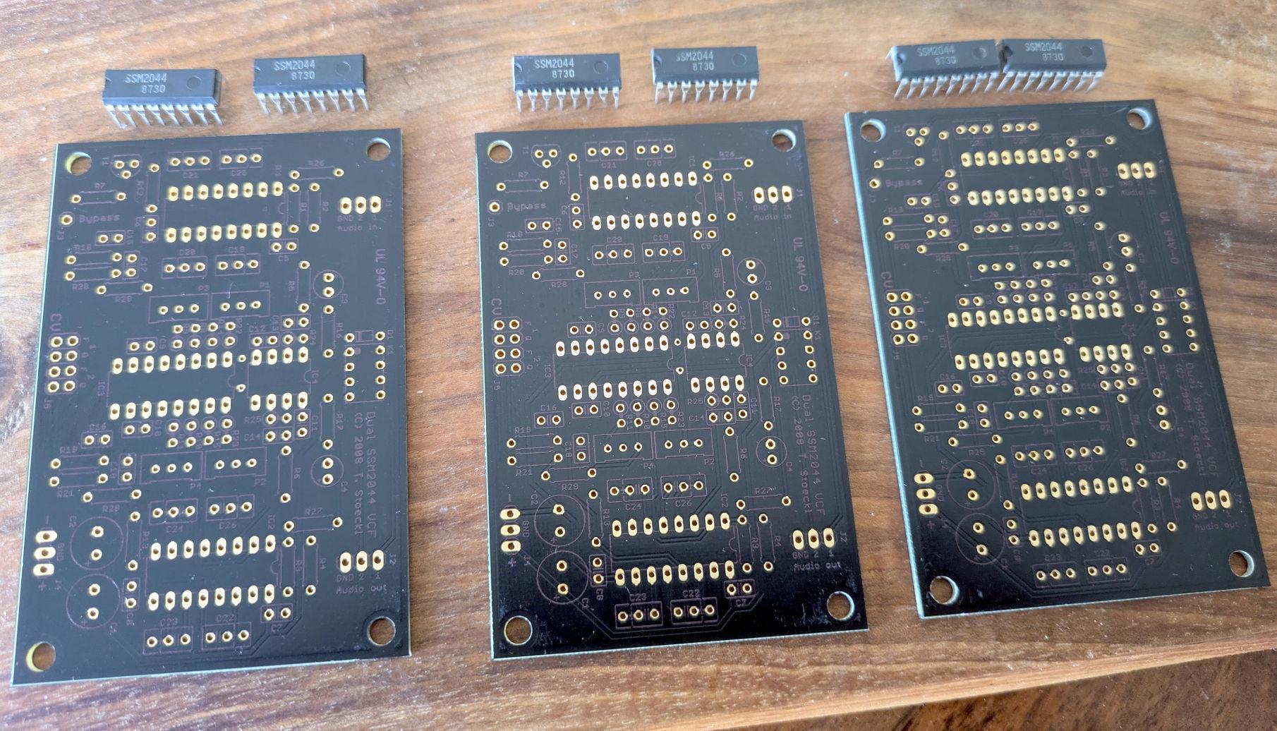
Hi, I might have what you're looking for. Would you be interested with original 2044 chips too? edit: found, PCBs from Seppoman and chips from Wilba
 1 point