Leaderboard


Popular Content
Showing content with the highest reputation since 01/28/2021 in all areas
-
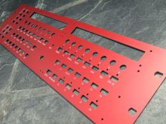
Necro bump, here are some more hi-res pictures, as the ones over at MI forum are just thumbnails.5 points
-
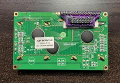
I read a lot of guides. Successfully compiled ASM code. The OLED display works well with an 8bit driver. If anyone needs the firmware, here is: setup_sammich_sid_8bit.hex3 points
-
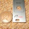
Hey man. It's actually an FR4-Standard PCB. Non aluminium. But seems pretty robust anyway.2 points
-
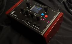
Hello friends. I am Rolf and I would like to share my latest DIY project "Jeannie" with you. It is an 8 voices polyphonic synthesizer based on a Teensy 4.1 board. I started doing it last summer. Now I have built an effects circuit for the synthesizer. "Jeannie" DIY Synthesizer Effect circuit Video The Fx menu in the synth is almost ready. The new one is still missing Display of the parameter values after a program change. There are more videos on my youtube channel: https://www.youtube.com/channel/UCXQSpP0qn5MXSkyDo6PZ4Cw Greetings from germany. Rolf2 points
-
2 points
-
2 points
-
I built my MB-6582 last year, so relatively recently... In the process I pieced together a few handy references that helped me with my build... Good luck with yours... Planning the cost of a build, based on various component options: PCB Sets are still available here: https://modularaddict.com/shop-by-brand/midibox-ucapps-de Nice pre-made Aluminum panel sets available here: http://thebeast.co.uk/?product_cat=midibox As a bargain basement alternative to aluminum, you could have panels fabricated as if they were PCBs, which saves a ton: If real SIDs are too difficult to find and/or too expensive, take a look at the best clone options: How to program your Microcontrollers: ...Or just buy some pre-programmed chips: Where to get the "Just Right" power switch: Which SID filter capacitors to use: A useful voltage testing guide: There are many power supply options available, but this one is by far the easiest: THE definitive guide for making the control surface: A nice little PCB that simplifies Char LCD Wiring: A useful way to join the boards together: Optional Encoder Backlighting:2 points
-
Unit has been finished this morning, and cheers from Berlin! Would love to get a serial, even though i missed #422 points
-
A quick video demo, made by a friend. I just gave it to him like that, without much explanation. The user manual is still not ready (blame me) but he managed to catch the thing even though he only used a few of the features.2 points
-
For anyone that's been considering the ARMSID or ARM2SID, but didn't want the headache of having to maintain a working C64 to configure them, the guys at Retrocomp have come up with a novel solution for you... It's basically a DIY Arduino shield that enables you manage the whole configuration process through a simple terminal Source code available here: https://github.com/nobomi/Arduino-ARMSID-configurator Partial kits available here: https://retrocomp.cz/produkt?id=67 I don't know about the rest of you, but for me, the SID Clone wars are over and the clear winner is ARMSID. 1. The sound is very close to the real deal, in either 6581 and 8580 mode. IMHO, it's even better than the SwinSID Ultimate (listen to examples above in this thread) 2. The design is by far the cleanest and sleekest, all the way through to packaging, delivery, quality documentation, vendor support, etc. 3. The size and form-factor are very close to a real SID, so it will fit anywhere a SID does, unlike some of the clunkier clones 4. It's jumper-less and auto-detects the correct SID emulation mode, depending on the input voltage It receives. The mode can be overridden however, using the aforementioned config editor (imagine an 8580 in a Breadbin or a 6581 in a C64c / G). 5. The price for an ARMSID is absolutely reasonable and you can save a few $$ if you need dual SID pairs, by going with the ARM2SID 6. It provides support for analog paddles if you happen to have a real C64 And NO, I am in no way affiliated with Retrocomp or the ARMSID, but I just think these guys have done a terrific job on this... Kudos...2 points
-
The 1st draft in 3D The board is roughly the size of a laboratory card in euro format (160 x 100). The Fx module is simply plugged onto the back. The current prototype Greetings from germany. Rolf2 points
-
Thank you for making this clear, Martin. The question is still unanswered if itˋs possible to use Vice via Asid with a Midibox SID to configure DSP Clone Settings instead of a real C64.2 points
-
Hello, it is quite different. If you use ARM2SID with the second SID2 socket, connect it with provided 6 pin wire, and configure it to SOCKET configuration (it is by default) it behaves in 2 SID sockets as 2 SIDs. No doubling the output, ARM2SID has enough processing power so it can process 3 SIDs inside, so in 2 SOCKET configuration it processes both SIDs (the chip select and R/W is brought to the main chip by the wire) and sends the second SID audio back to the SID2 socket by another wire. Thus ARM2SID in socket configuration with SID2 socket and the 6pin wire behaves exactly as 2 ARMSIDs. You can set in configuration one as 8580 and the other one as 6581 or adjust filters and digifix independently. The option on picture that dwestbury published above with directly connected wires is for implementing ARM2SID to C64 or similar and when you provide all the addressing by wires, it does not need any stereo adapter and it supports stereo or 3SID or FM emulation, but it needs the additional wires for addressing. With the 2 SOCKET configuration, it can work only as a stereo, not dual mono as jjonas says. The second SID2 socket provides input and output for the 2nd SID emulation, even it is an empty socket conversion placeholder. Best regards Martin Lukasek ARMSID technical suppot2 points
-
Here's a tip for anyone who wants an easy way of having raised lettering on their 3D prints with a different colour to the case itself. Print the case with lettering with the same colour filament you want the raised lettering to have. Paint or (spray paint is probably best) the entire case in the colour you want the case to be. Then simply sand the lettering with sand paper and the original filament colour will come through. I saw this method posted in a facebook Flight Sim group where a user 3D printed his own Boeing 737 panels:2 points
-
Here is mine :) Only heard about this project last week and now I'm the owner of this beautiful beast. Thanks Peter and Andy for all the help (me spamming you) in the last few days :)2 points
-
maybe its the Ripple off the PSU about your PSU - reichelt specs is saying : "Ondulation résiduelle : 80 mVcàc" i guess this is not a 50Hz ripple but HF ripple... --- i guess some small cap (100nf, 10pF) and a big Cap (depends on the load, use for example a 100uF and a 2200uF) on the output off the PSU would reduce that "ripple"... * maybe that caps are not enough and you need some more filtering (coil, resistor, lpf...) but i would start with some caps... the connections in your 2nd picture are not necessery - i guess (dont seeing the whole picture, but i think so...) --- so picture 1 is correct. by the way - its only the last LED that flickers? maybe you have to terminate the DO line on the very last LED off the Chain with a 10K resistor to 5V or Ground. else it could be a software problem, when the software loops thru the LEDs, and when it comes to the last one it jumps to the beginning off the chain... try to programm in the ng code one more LED (which in reality not exists) - so you can be sure that this is not a software bug... - but dont ask me about ng-programming --- no glue about that. - mike.1 point
-
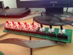
Hello, first of all thank you for your previous answers. I haven't fixed the problem with the pads yet. I'm focusing on another problem for now: with the LED rings. with 16 led ring of 16 led no problem. when I add more, the LEDs flicker. https://youtu.be/HyLkVeFtALw?si=gT09lbCxEwLRmHt8 I read here: http://midibox.org/forums/topic/21095-lre-4x1-breakable-rgb-led-ringrotary-encoder-pcb-bulk-order/?do=findComment&comment=184155 FantomXR had flickering problems, solved with a 10uf capacitor. Should I add a 10uf capacitor at the input of my LED ring cards? (as in the image below) (C129) To understand my configuration see the pdfs: LEDRING: https://drive.google.com/file/d/1XpDQBUE42IqXpXicO--B2gfIoNQDh5ga/view?usp=drive_link “power card”: https://drive.google.com/file/d/1NJ-H-QXD-tl9rU6nbYdEh2Q4jFqjWt6b/view?usp=drive_link I made a PCB that I call a “power card” that I supply with 5v 10 amps. The J2 connector of the "power card" is connected to J4b of core 32. Connector J44 of the first OLED card is connected to J3 of the “power card” Connector J45 of the first OLED card is connected to J4 of the “power card” Connector J44 of the second OLED card is connected to J5 of the “power card” Connector J45 of the second OLED card is connected to J6 of the “power card” etc.. Thank you1 point
-
Hi all , Was wondering about opening a KiCAD Section in the wiki? For tutorials , midibox libs etc... where should i put it? regards, JK Edit : A Frontpanel designer section could be useful too ?That's a soft that i think most of us use? Maybe create a "Softwares" Section?1 point
-
j2/j17 should do the trick yes.1 point
-
the ssd1306 oleds i received where 5V tolerant... the ws2812b is also in a range from 3.3-5.3V, dout modules also needs 5V... so your reichelt psu should do the job, and you could power them directly from the psu... but i guess you power them with the ribbon cables from your core... i dont know what Core you will use? if you use the WCORE from midiphy, then you may ran into some problems when using a external 5V PSU, see this topic: https://forum.midiphy.com/d/151-wcore-non-usb-powerd-but-still-use-as-usb-device/5 also if you are unlucky you will get walking lines on your SSD1306 screens... then it best it would to buffer each D0 D1 Clock... Pins, which are done for example in this module: http://wiki.midibox.org/doku.php?id=displaydriver-smd a plus is then you can then use more then 8 screens!1 point
-
1 point
-
@ pusbutton: the LEDs in the shematic are REVERSED for example look into: http://ucapps.de/mbhp/mbhp_doutx4_32leds.pdf but in the board itself the Silkscreen for the Diode is painted correct - so if somebody just solder the PCB without looking into the Shematic - all is good, when someone look into the shematic he may be confused a bit. what type off Switch are using here > type it on the silkscreen - like you did on the Potentiometerboard. because: i see in the footprint its a le mec > then there are different types, with different Switch contacts - like you see here: 5GTH9 + 5ETH9 will work, while 5GTH9 with inbuilt LED will not work off course... i for me find the correct switch matching to your PCBs Footprint-Pinout - a bit hard... so label the type.... the rest off the PCB looks ok.1 point
-
Hello, Peter made an awesome video (4k quality!) demonstrating the assembly of the following modules Euroceiver (line driver receiver in the rack), power distribution A1 Expander (AOUT based on MAX5500) D1 Expander (DOUTX1 for gates plus protection) D2/D3 Expanders (likewise for clocks and triggers) Feel free to use this thread for any discussion or troubleshooting. Have fun building your modules!1 point
-
at RGB-Leds > i dont know, how many you will use? which coremodule you will use? is it eurorackbased > and eurorack powerd? Which RGB-LED you will use - and what is the Voltage it needs? and so on.... i looked into your files.... some notices: @BP: dont connect the mountingholes to ground, or any other potential, best would be to make a keep out-area (sperrfläche) arround it, like i did for example here: http://wiki.midibox.org/lib/exe/fetch.php?w=600&tok=f96292&media=phatline:daw-btn-3d-b.jpg since you can plastic and/or metall standoffs to mount that pcb to the panel, you would need at least 6mm or more keepout-area.... background: you want to avoid groundloops over the frontpanel, and the risk of a electrical shock is less.... The LEDs in the diagram are connected false, the tip off the arrow should always be connected to the ground. (you should turn them 180°) which buttons do you want to use? please check the pinout off them... for me it happend that i did not connect the correct pins, so double check this.... why you made those cuts on the 4 corners? its better to make them rectangular - background: if you panelize the pcb, you have to draw a V-Grove line, the machine can only Grove in 90°, the idea, is to put 2 off this boards on one 100x100 PCB so you can save money on FAB.... way more oversight you have if you use a Groundsymbol... instead off paint Lines to a ground inside your shematic... look into "control" to see what i mean...also it makes it easyier to work with groundplanes, since this needs a NET... @Control: please open this file:Control.zip the same like above, and, you dont need that vias next to PIN 2 off the switches > Pin 2 is a via itself.... - same for Pin 1 off P2, the Problem it did not fill without your Vias: because you dont used a Ground-Net.... Pin1 - which is labeld as VDD (+) was connect to all your buttons and the pot (which is a Encoder)... normaly we connect them to ground..... VSS is ground.... so i exchanged the whole thing.... i dont know iff this is then still correct in your big picture- wiring diagram.... how ever thats the way i would make it - at least iff the Pin-Labels off the IDC Connectors are right... you should put the 4 mounting holes in the shematic, so you dont loose them when updating the PCB Also dont label your Encoder with Pot or RV >>> this is not a Potentiometer... that confused me until i realized this is a Encoder.... also the google-Drive files are a bit corrupt - the footprints where not assigned to the Shematic symbols...... when you save the project and upload it somewhere - zip it inside Kicad with "Projektdaten archivieren" - dont know the french word for it. -please overwork also your BP like/or simular like i did.... @Fader 1/2.... please open this file: Fad_2.zip shematic: also better use GND and VDD Nets.... more oversight! if you dont use a Pin off your IDC-Header (P5), then "x" them out with the blue "x" on the right side off your editor.... For what are those outer Mounting holes? they are too near to the Faders...make the pcb bigger so there is space for a Spacer/standoff, or use only the 4 inner mounting holes... which i think is enough.... again better 90° corners.... fill out your Shematics "Circuit-Field" right down - dont know the englisch or french word for "Plankopf" ... by the way you can design your own "Plankopf", so you dont see there thing like "KiCAD E.D.,A kicad 6.0.10......" keep out for mounting holes again... (see PB) dont make outher planes on VDD(+) ... mostly there can happen problems when mounting the thing to a panels, better use Ground-Planes... When looking on your FAders Footprint, and on the DAtasheet for the RA6020F then i am not sure iff the pinout is correct (the datasheet is bullshit...) but i guess you imported the Symbol and Footprint from mouser or something....then i guess its oky.... also use the design-rule check function (in a shematic and PCB-Editor) i did not looked in the other kicad-projects... but i guess its the same - a bit overwork needet..1 point
-
Hello all Selling my midibox sequencer including breakout box. The sequencer is fully functional, from a non-smoking household. Has never been used for live performances, only studio use. The breakout box is a bit obvious DIY but fully functional. You need a free slot in the modular system for the +-12V power supply. Selling price 1350,-€. best regards rbv2 https://www.ebay-kleinanzeigen.de/s-anzeige/midiphy-sequencer-v4-midibox-stepsequencer/2241157248-74-42571 point
-
Oh, wow, I totally missed that! Thank you!!! I wasted an entire day rummaging around and didn't manage to see that :) Just in case others run across this: You want 4SPI configuration, not IIC like I have in the pic. The number of screens you have must match the configuration you set in the bootloader, otherwise you get noise, and won't be able to write to all the lines/columns Also easy to miss, but for the 1306 RES connection, you need to wire it up like this (again, connections on your 1306 PCB): GND -> 10uf cap -> 1k resistor -> VCC. Once done, RES will be tied to where the cap and resistor meet (like this) It wasn't clear to me how to actually use the bootloader for the STMF4 board, but it's essentially: Plugin your board as you normally do Open MIOS Studio Click Browse and choose the mios32_bootloader app (download here) Click Start. If it won't complete, try unpluging/pluging the board and trying again Unplug/plugin the board In the MIDI IN and MIDI OUT sections whatever app you had prior to all of this might be listed, but it doesn't actually exist (and it shouldn't). That's why you now see the error "No response...". The new app, MIOS32, took its place and you need to refresh to see it. Click Application -> Rescan MIDI Devices Click Understood in the pop-up (this will make your old app disappear, and the MIOS32 app show up) Change MIDI IN and MIDI OUT to MIOS32 Enter these one by one into the input box: (send a command to MIOS32 application). Keep in mind lcd_num_x must match the number you have chained: set lcd_type GLCD_SSD1306 set lcd_num_x 1 set lcd_num_y 1 set lcd_width 128 set lcd_height 64 store Yah. Bootloader is done. Time to restore your app in MIOS Studio: Click Browse and choose whatever app you want, like midibox_ng Click Start. Like the bootloader, if it won't complete, try unpluging/pluging the board and trying again Unplug/plugin the board Now for some test display data. Lets set some values for your SSD1306 OLED's in MIOS Studio: Click on Tools -> MIOS32 File Browser Click Create File Create some name like LCD.NGC Click Update Click on the file you just created Click Edit Text and add the following test example: RESET_HW LCD "%C" LCD "@(1:1:1)A23456789012345678901234567890" LCD "@(1:1:2)B23456789012345678901234567890" LCD "@(1:1:3)C23456789012345678901234567890" LCD "@(1:1:4)D23456789012345678901234567890" LCD "@(1:1:5)E23456789012345678901234567890" LCD "@(1:1:6)F23456789012345678901234567890" LCD "@(1:1:7)G23456789012345678901234567890" LCD "@(1:1:8)H23456789012345678901234567890" Click Save You should now have 8 rows and 21 columns of text. If you need to flip it 180 degrees, you can redo the steps above and add set lcd_type GLCD_SSD1306_ROTATED before you store.1 point
-
pcb arrive, soldered 4 off them (12 channels) - the 4 others i make a nother time. (24ch in total) the display drivers from Andy work great again! the midibox code is working, the max for live patches too. (at least for this state i am happy to get automaticly the Channels names, and the Macronames!!! hell yeah!)1 point
-
ok i am in austria... so maybe a other one?1 point
-
Jeannie & Volca in Love Link: https://www.tubeohm.com/1 point
-
I get the same, but one trick is to highlight the entire contents and "print" the page to PDF. Then you should get the images in line. Best, Andy1 point
-
Well done!1 point
-
.jpg.5582e6d3d209f1e5f7eeb8c685b78cb8.jpg)
From the album: Antichambre "stuff and work"
1 point -
Very pleased to report that my 6582 has made its first noise -- notes played on the MIOS Studio keyboard trigger the one (so far) 8580 to play that lovely reedy default patch. This is delightful. Thanks for all your help so far, all y'all.1 point
-
Almost there (stay on target).1 point
-
If you think an available commercial device can fulfil your needs, then get one! DIY is a different thing. It is potentially more expensive and you have to put in the tools and effort to finish things, but the journey can be very rewarding and sometimes you can obtain tools that are not found elsewhere, often for the very reason that they would be impractical or uneconomical to produce in scale.1 point
-
Well done! Are you building the CS too or somethin else?1 point
-
i made a list for needet hardware: 1x this can handle the Encoders and Buttons + 16 Displays : http://ucapps.de/mbhp_dio_matrix.html 1x this can handle 32 Displays: http://ucapps.de/mbhp_dout.html 1x this should handle 8 Displays(+the Discovery board and all the parts of course...) http://ucapps.de/mbhp_core_stm32f4.html hmm makes 56 Displays. so if you want 64 you add a 595 by yourself with protoboard, or take a nother DIO-Matrix... 1x SD-Card (+Fullsize adapter) of different Fabricates --- very often that one is not working i have 2 of this -and booth are working: https://www.mouser.at/ProductDetail/SparkFun/COM-15107?qs=0lSvoLzn4L%2B%2BrzcqjOiTEA%3D%3D 64x Pinheaders that are sitting strong (or take hotglue) in order to better repear or swap or debug the LCD from your cables A lot of cables... i dont know how big the desk is, and whats about the cable length is (really dont know where the limit is?!) And very hard to find - this tiny Screws and Nuts for the LCDs to mount(they are not M3!), if you go ali express then you wait a month or 3... and like you said a 3.3V Voltageregulator that supply with ease 1.5 to 2A, and psu that deliever that too...1 point
-
there is an an entire bank of 16 resistors for the LEDs - if you use anything but red the brightness can vary a lot so 220 Ohm might not be suitable. I have white and they are way too bright i need to open it up and change them tbh! worth playing with resistor values here - higher resistance, dimmer LEDs.1 point
-
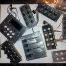
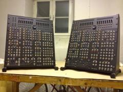
Congrats on building the momentum and seeing positive results... It’s an inspiring project for sure. Good luck with the remainder of your build. Looks like you have the original (Red Color) SmashTV Base PCBs? By the time I got around to doing my builds (last year) the only boards available were from Modular Addict (in signature Black). Cheers1 point
-
For anyone that happens to be based in the US, I still have plenty of extra ICs, including pre-programmed PICs. Shoot me a DM if you're interested...1 point
-
Quick test for CC automation. The HAARP is only connected to my laptop and Ableton Live is running. Live gives the sync. Only the Drum Track is programmed. I play with 4 differents clips. There's 3 synth used, BAss, Saw and Choir they are some of the basic provided with Ableton, no sequence, direct input are activated on the synth tracks. Preset, Mute change, and some of the parameters of the HAARP are automated, by a previous MIDI record.1 point
-
 This little pin converter from @Altitudereally cleans up and simplifies the character LCD wiring.1 point
 -
 Love these encoder backlight PCBs by @d0pefish1 point
 -
Hi Bruno. Whenever you'll be ready, you can pass the manual to me for reviewing. BR, Flavio. PS: any news about the enclosure?1 point
-
 Can you share yourvpot pcb1 point
 -
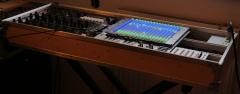
Hey people, in this thread I'll post time after time updates about my latest keyboard build. Also I'll use this thread to publish eagle-PCB-layout-files and schematics. But please be patient. Uploading and documenting all that stuff is highly time consuming and it's right before christmas. So far everything works great, but the work under the hood was really time consuming because I used a lot of modules... some available from Tim, some I did on my own. I think modules are great if you need high flexibility... and all the modules are working perfectly. But if it comes down to save space and wiring, modules are a mess. Anyway... here we go: So I was tired using a laptop, a soundcard, tons of cables and all that stuff on stage. So I thought: What if I put the computer into the keyboard? It was quite successful. I used an Mini-ITX mainboard from Gigabyte, an i5-3570k (I'd go with a better i7 if I hadn't had that i5 before) with a low profile cooler. The mainboard is equipped with 16GB of RAM. Also I integrated two Samsung SSDs with 500GB each. The whole thing is powered through a Seasonic SS250U power supply. As soundcard I use a PCIe card from RME HDSPe AiO. Because this only has two audio in/outs, I also bought two expansion-board that gives me another four in and outs. The first two analog-outs are going through a self-made DI-box with high quality LEHLE-transformer... absolutely great stuff. This DI-box features also a 20dB PAD and a GND-lift. Let's hand over to the MIDIbox-side: I use two cores. One of them only takes care of the keyboard scanning. It was very important to me to not make a compromise on this. This core is connected via MIDI-out to the MIDI-In of the other core. Both cores are STM32F4 based. I used my own PCBs for that. @TK. Is it a problem if I publish those schematics and layouts for the core? I know that the official core is not published yet to cover the costs for PCB production and development. The PCB I developed only contains the connectors I need: it has J8/9, J19, J10A, J11 and J30 (as far as I remember... don't have it right in front of me at the moment). I tried to get a smaller footprint of the whole PCB. It also features a MicroSD-card slot instead of the SD-card-slot in the official PCB. My keyboard has nine analog faders build in... they are not motorized. I don't need that for now as they are much more expensive and also take more space. Also they are more difficult to wire up and connect. At first I did some tests with the AINSER8. But after a while I gave AINSER64 a try with the result, that it has less jitter than the AINSER8. The faders are a lot more quiet than with AINSER8. As I needed more than 16 analog inputs this was needed anyway. I power the AINSER64 through the core and the core receives it's power directly from the seasonic-power supply and NOT via USB. I needed some LEDs to visualize the status of my faders. A long long time ago I wanted to start another LED-fader-project but never finished it. So I had a lot of those LED-bars laying around... I took them and putted them into the board... works and feels great! On the next revision I'd try to use one big PCB for all 9 LED-bars to safe wiring and time for mounting. Now I used two 10pin IDC connectors (with only 8 pins of each are connected to the LED-bars = 16 LEDs). I did some mistakes when assembling the LED-PCBs... now sometimes some LEDs don't work... anyway... I can live with that for now. @TK. How about the WS2812 or APA102-LEDs? Do you think it's worth using them as LED-rings? I'm not sure what the status is and if they are supported in that way by MIDIbox. Would be a great alternative but they take a lot more space than 0603 SMD LEDs of course. The LED-bars are connected to small modules I did based on @novski designs. Those small modules are equipped with one or two DIN / DOUT modules. They work great and the advantage is, that I can stack them directly on the pinheader of the PCB... no cables needed! A bit hotglue and you are ready to go. I also have 8 encoders on each side of the keyboard. The right side is not connected yet... not sure if I do need so many encoders ;-) Of course they are also equipped with LED-rings. While the LED-bars where assembled by factory (I think I used SEEED) the encoder-rings came blank... so it took me a looooooong time adding 128 0805 SMD LEDs to all PCBs... at this time I had not have my reflow-oven... with this one that might be an easy task :-) The encoders (and the switches of the encoders) are connected to a 4xDIN board from novski. I'm not sure if this board really works well. Sometimes if I set debug on, MIOS lists tons of EVENT_BUTTONS. I'll need to investigate that. Maybe it has something to do with RC1 / RC2 lines. Underneath the faders I have a set of 2x8 buttons. I'm not really happy with them. I did the caps by myself and this was a really shitty work... next time I will use tact-switches that already come with caps f.e. TC011 like I did in the 1x8 button-row right in front of the player / underneath the display. For the buttons I designed a DIO-breakout-board. This breakout-board splits the matrix configuration of the 2x8 pinheader of the DIO-module to a more usable 2x5pin header-configuration with the row on pin 1 and the switch-lines on 3-10. With this way it's very easy to connect tons of buttons to a MIDIbox. . Same for the LEDs of the buttons. I used a DOUT-module with ULN2803 as LED driver (btw. I drive all LEDs with ULN2803 and do NOT use a resistor before or after the LEDs. As those LED-lines are scanned, a limiting resistor doesn't seem to be necessary). That's mainly it... the keyboard has two MIDI I/Os on the back as well as four pedal connectors for two switches and two expression pedals. The touchscreen in the middle is a 10" capacitive screen... that works awesome!! That's the story for now... like I said I'll try to keep this thread alive and add the PCB layouts and schematics later on. Thanks for reading!! Best, Chris1 point
-
Hi everyone ! I experienced the same problem, and The Ancient One's solution works perfectly for me. I changed the 220R resistors to 68R for R21 and R22. Now the 9090 detects the signal without any issue. Thank you a lot Michael ! Théo1 point
-
From the album: Jojjelito's pixx-o-stuff
The woodwork part of the case is done. After getting clad with black foil the new working name was temporarily set to Black Satan. Darth Vader stopped by for a cup of tea and wanted one.© Johan T
1 point -
From the album: Julian F
1 point