Leaderboard


Popular Content
Showing content with the highest reputation since 08/14/2021 in all areas
-
I read a lot of guides. Successfully compiled ASM code. The OLED display works well with an 8bit driver. If anyone needs the firmware, here is: setup_sammich_sid_8bit.hex3 points
-
Hey man. It's actually an FR4-Standard PCB. Non aluminium. But seems pretty robust anyway.2 points
-
2 points
-
2 points
-
I built my MB-6582 last year, so relatively recently... In the process I pieced together a few handy references that helped me with my build... Good luck with yours... Planning the cost of a build, based on various component options: PCB Sets are still available here: https://modularaddict.com/shop-by-brand/midibox-ucapps-de Nice pre-made Aluminum panel sets available here: http://thebeast.co.uk/?product_cat=midibox As a bargain basement alternative to aluminum, you could have panels fabricated as if they were PCBs, which saves a ton: If real SIDs are too difficult to find and/or too expensive, take a look at the best clone options: How to program your Microcontrollers: ...Or just buy some pre-programmed chips: Where to get the "Just Right" power switch: Which SID filter capacitors to use: A useful voltage testing guide: There are many power supply options available, but this one is by far the easiest: THE definitive guide for making the control surface: A nice little PCB that simplifies Char LCD Wiring: A useful way to join the boards together: Optional Encoder Backlighting:2 points
-
Just a small necro-bump :-) …by now we are roughly 150 people over there with some occasional chatting going on. Feel free to drop by!1 point
-
Hi all , Was wondering about opening a KiCAD Section in the wiki? For tutorials , midibox libs etc... where should i put it? regards, JK Edit : A Frontpanel designer section could be useful too ?That's a soft that i think most of us use? Maybe create a "Softwares" Section?1 point
-
1 point
-
1 point
-
@ potentiometer: looking good, but labeling the Holes is not necessery (i think) :1 point
-
That's absolutely glorious Peter! Nice work (as always!)1 point
-
You can leave off the USB, it's only an additional +5V power option selectable by jumper..1 point
-
Yes, absolutely. Please PM me for details, ideally including your location so I can give you a shipping quote if interested.1 point
-
Looks very nice and neat .I didnt know you are so busy with things . (Thank you for your support). I was working a lot with max/msp and m4l too. Its a lot of fun , but it takes a lot of time as well :) . Enjoy and keep up this amazing work.1 point
-
look into ng documentation if there can be set a offset for the middle position so it stays on a position... because pots directly to the core is always a bit random... better use for example: http://www.ucapps.de/mbhp_ainser8.html then you have less random values also check the quality off PSU...off course a faulty pot can be the reason too1 point
-
@ cherry: the switch itself you can get already from eg https://www.reichelt.de/tastaturzubehoer-c8099.html?ACTION=2&GROUPID=8099&SEARCH=*&START=16&OFFSET=16&CCOUNTRY=445&LANGUAGE=de&r=1&SID=967792150a00d890464504461a66ae529d97182e528c945af4544 caps: amazon, alibaba,.maybe.some thing like that: https://www.amazon.com/dp/B00FYO8EDC/ref=mp_s_a_1_5?keywords=flat%2Bkeycaps&qid=1675511770&sr=8-5&th=1&psc=1 https://www.cherrymx.de/en/dev.html the low profile is maybe interesting....1 point
-
control hardware yes, if it is well documentadet on the wiki (shematic, board screenshot) I too work with kicad since decades... and very sucessfull now with my actual projects - i was wondering but i planed it in kicad, and most off the boards where working 100% out off the Box (pick and place JLCPCB), ok i had a design fault on one, but that was solved with a wire-done. actual projects http://wiki.midibox.org/doku.php?id=triggermatrix5 http://wiki.midibox.org/doku.php?id=daw-ableton http://wiki.midibox.org/doku.php?id=openpad software: cant help, write my own Mios-based code, havent look into MidiboxNG - since it is a script, for me more easy to write it directly in C, (need to understand all, else i understand/learn nothing...) - so no help from this side had good expierences with jlcpcb... also with the Pick and Place service FrontPanels: maybe cheap CNC-Laser-Cutting from pcbway? https://www.pcbway.com/rapid-prototyping/CNC-machining/CNC-Laser-Cutting-Services.html suggestions? Maybe use Eurorackformat, so it can be used outside of your box too? suggestion, where usefull (wo sinnvoll) use J89 Serial Chain directly onboard (like encoder with ledring boards) to reduce wireing - a simple button board dont needs that of course.... *** if you go the Serial Chain way, then buffer the Serial chain on each module to keep the digital Signal Quality intact (very necessery) *** buffer: search for SN74LVC1G17DBVR in this shematic: http://wiki.midibox.org/lib/exe/fetch.php?media=phatline:blm16x16-shematic.pdf maybe use pick and place ready smd technologoy like i did: that makes it smaller, and less to solder, less to debug, the plastic packages stays in china, more economical special when ordering more pcbs, by that of course a module should fit all the boxes (a exotic 1 man needs it module 10times fabricated is 9 too much...) i think i dont have to say, that you should choose "Basic" Parts, and not "extendet parts" on JLCPCB, - off course on most modules you have at least one or two extendeet parts... but for example a DINX4 or DOUTX4 can be made with basic parts only... but when you also want to pick and place all the pin headers - these are extendet parts, how ever ... you may look on my last modules a bit http://wiki.midibox.org/doku.php?id=tm5-dindoutgate http://wiki.midibox.org/doku.php?id=doutx2dinx1 if you use long cables to your Displays + u use more displays then one - on the modules, use a display driver (no more walking lines) http://wiki.midibox.org/doku.php?id=displaydriver-smd what else? if you make ground or other PCB-Planes, then setup kicad that it make 1-2mm space arround solderpoints - else the Soldering Man could make shorts, or electrocemical oxidations or solder flux-low-residance could make there some problems (after years), special when the Solderstop-Pain is scratched a bit... ... and so on... PS i hate this wooble feeling off this LeMec Buttons (the last board you posted) - these Buttons are not good (for my taste) I love to work with this ones: https://www.reichelt.de/at/de/eingabetaster-schaltspannung-24v-fuer-led-sw-dtl-2-sw-p7248.html?&trstct=pos_0&nbc=1 they are expensive, but they last decades (in use, and also if you order 300 off them and let them lye arround, after 15 years they still work) They have good CLICK, like a mechanical Keyboard. your leMec Buttons are like a mixture off Rubberdome and "i have to touch this buttons into one direction X=0 Y=0 else it want switch" or you could use: https://www.midiphy.com/en/shop-details/140/4/5pcs-matias-quiet-click-tactile-switch- they are cheap but big... (aka take away a lot of Frontpanel space) or maybe you use cherry switches or simulars.... they are all 1000% better then this leMecs... ( you notice i hate them)1 point
-
this will take a while - look into the forum in 5 weeks or so. i need the PCB to make a new version off Triggermatrix (http://wiki.midibox.org/doku.php?id=triggermatrix4) the Frontpanel is not a generic MatrixController thing - it has 17 Displays, 8 Faders, some rotarys and buttons, the Software for this is not a normal Midicontroller-code (aka Midibox NG) - its my own creation a sequencer based on MIOS. - but if i not make a shematic mistake, the pcb should be usable like the orginal BLM16*16+X in other Midibox Projects.1 point
-
adafruit rubber button 4x41 point
-
Very cool….well done.1 point
-
Oh, wow, I totally missed that! Thank you!!! I wasted an entire day rummaging around and didn't manage to see that :) Just in case others run across this: You want 4SPI configuration, not IIC like I have in the pic. The number of screens you have must match the configuration you set in the bootloader, otherwise you get noise, and won't be able to write to all the lines/columns Also easy to miss, but for the 1306 RES connection, you need to wire it up like this (again, connections on your 1306 PCB): GND -> 10uf cap -> 1k resistor -> VCC. Once done, RES will be tied to where the cap and resistor meet (like this) It wasn't clear to me how to actually use the bootloader for the STMF4 board, but it's essentially: Plugin your board as you normally do Open MIOS Studio Click Browse and choose the mios32_bootloader app (download here) Click Start. If it won't complete, try unpluging/pluging the board and trying again Unplug/plugin the board In the MIDI IN and MIDI OUT sections whatever app you had prior to all of this might be listed, but it doesn't actually exist (and it shouldn't). That's why you now see the error "No response...". The new app, MIOS32, took its place and you need to refresh to see it. Click Application -> Rescan MIDI Devices Click Understood in the pop-up (this will make your old app disappear, and the MIOS32 app show up) Change MIDI IN and MIDI OUT to MIOS32 Enter these one by one into the input box: (send a command to MIOS32 application). Keep in mind lcd_num_x must match the number you have chained: set lcd_type GLCD_SSD1306 set lcd_num_x 1 set lcd_num_y 1 set lcd_width 128 set lcd_height 64 store Yah. Bootloader is done. Time to restore your app in MIOS Studio: Click Browse and choose whatever app you want, like midibox_ng Click Start. Like the bootloader, if it won't complete, try unpluging/pluging the board and trying again Unplug/plugin the board Now for some test display data. Lets set some values for your SSD1306 OLED's in MIOS Studio: Click on Tools -> MIOS32 File Browser Click Create File Create some name like LCD.NGC Click Update Click on the file you just created Click Edit Text and add the following test example: RESET_HW LCD "%C" LCD "@(1:1:1)A23456789012345678901234567890" LCD "@(1:1:2)B23456789012345678901234567890" LCD "@(1:1:3)C23456789012345678901234567890" LCD "@(1:1:4)D23456789012345678901234567890" LCD "@(1:1:5)E23456789012345678901234567890" LCD "@(1:1:6)F23456789012345678901234567890" LCD "@(1:1:7)G23456789012345678901234567890" LCD "@(1:1:8)H23456789012345678901234567890" Click Save You should now have 8 rows and 21 columns of text. If you need to flip it 180 degrees, you can redo the steps above and add set lcd_type GLCD_SSD1306_ROTATED before you store.1 point
-
ok next step... "Mute" & Solo Buttons needs some external DINX and DOUTX boards (in order to make the SRIO-Gain short)1 point
-
pcb arrive, soldered 4 off them (12 channels) - the 4 others i make a nother time. (24ch in total) the display drivers from Andy work great again! the midibox code is working, the max for live patches too. (at least for this state i am happy to get automaticly the Channels names, and the Macronames!!! hell yeah!)1 point
-
Here's the gerbers for the MB-6582 panel set pictured in this thread... Please credit @listen202 and @Manu29 for their efforts... _MB6582_Panel_L202-Manu.zip _MB6582_Rear_L202-Manu.zip1 point
-
i guess not the pyboard uses a 12Mhz external crystal? and Mios32 needs? look at the Pinout: http://wiki.midibox.org/lib/exe/fetch.php?media=antichambre:pinout_compare_chart2.png a quick look at for example the SD-Card Pins - of the pyboard and on Dipcore or Discovery stm32F407VG - says that the use other GPIO to do things... So yes you may flash that pyboard, but the Mhz might not be right (aka need to replace the oscillator) So yes you might run MIOS afterwards... but you cant use for example the onboard SD-Card - because it is wired to other pins... you have to DO the work that antichambre did (change the GPIO ports in MIOS, make a new toolchain, and that is a Job for someone who knows what he does - i would be very happy if i could do that - or someone introduce that skill to me- but i dont have any glue about that)1 point
-
Oh si il est polyphonique ! Tu as 8 voies simultanées que tu peux router vers un canal/port midi dédié ! - Yes it it polyphonic, you have 8 simultaneous voices you can route on a dedicated midi channel/port !1 point
-
So 16 banks in total, right? I'll will try something... After a bit of head scratching and a few glasses of rhums, here you go: first the .ngc : EVENT_BUTTON id= 1 type= Meta meta= DecBank meta= RunSection:1 button_mode= OnOnly #Bank decrease EVENT_BUTTON id= 2 type= Meta meta= IncBank meta= RunSection:1 button_mode= OnOnly #Bank increase EVENT_LED id= 1 range= 1:1 radio_group= 1 #bank1 EVENT_LED id= 2 range= 2:2 radio_group= 1 #bank2 EVENT_LED id= 3 range= 3:3 radio_group= 1 #bank3 EVENT_LED id= 4 range= 4:4 radio_group= 4 #bank4 now for the .ngr : ####### Section 0 ####### if ^section == 0 log "running section0" #initialize all banks to 1 log "call bank 1 for all parameters" set ^bank 1 exit endif ######################### ########## Section 1 ########### #tests for the current bank and lights the corresponding LED if ^section == 1 if ^bank == 1 log "bank 1 selected" set LED:1 1 elseif ^bank == 2 log "bank 2 selected" set LED:2 2 elseif ^bank == 3 log "bank 3 selected" set LED:3 3 elseif ^bank == 4 log "bank 4 selected" set LED:4 4 endif exit endif ################################ I hope it works for you, at least, it behaves as wanted here.1 point
-
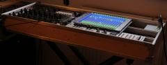
Hi everyone! Quick update here. I finally finished my controller and installed it in my small control-room. Here it is. I really like the way it turned out, i'm working with it since 2 weeks now, and it's a real bonus to the ergonomics. It still have room for improvements but that was expected and i will continue to work on it in the next future. I'd like to thank everyone on this forum who helped me build this and a BIG thanks to TK and all the midibox team. Without this place I would have never been able to even start this project. Cheers, Thomas1 point
-
I get the same, but one trick is to highlight the entire contents and "print" the page to PDF. Then you should get the images in line. Best, Andy1 point
-
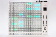 Oooh, it looks so high-tech!1 point
 -

From the album: midiphy MatriX
© 2021 latigid on
1 point -
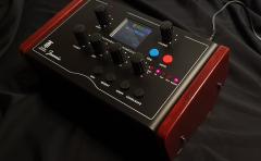
Hallo friends.. The DIY project is now over. Jeannie can be bought at tubeohm.com. Jeannie is an 8-voice polyphonic open source synthesizer kit with digital sound synthesis and digital filters based on a Teensy 4.1. For sound generation, the user has a variety of classic and band-limited waveforms at his disposal. A pool of 15 waveform banks with 63 different waveforms each offer plenty of space for sound experiments. A waveshaper with different characteristics provides for gentle to vicious sounding distortions. To match the waveforms, there is a digital 12dB multimode filter with fade function from low-pass to high-pass and a band-pass function. A 24-bit DSP effect module with adjustable parameters rounds off the sound synthesis. An integrated polyphonic 16-step sequencer provides for the playfulness of the small synthesizer. A total of 2048 sound patchesfrom 15 banks can be loaded and stored via an integrated SD card. A color 1.8 inch TFT display allows a clear menu structure and easy operation of the synthesizer. The parameters are entered via four rotary knobs below the display and an encoder for selecting the sound programmes and switching to the menu functions. In addition, there are six buttons for operating special synthesizer functions. properties • 8-part polyphonic DIY synthesizer • ARM Cortex-M7 processor 816MHz with 1MByte Ram • two digital oscillators per voice • 15 waveform banks with a total of 945 waveforms • 12 standard waveforms, some band limited • Noise generator (white and pink noise) • Oscillator modulation (XOR, XMOD, MOD, AND, OR, FM) • Waveshaper with different curve shapes • 2 LFOs for pitch and filter modulation with 6 different waveforms • 1 PWM LFO from 0.04Hz - 25Hz • Digital 12dB multimode filter with resonance and fade function (LP / HP / BP) • 2 ADSR generators 0.3ms - 12s with positive and negative control • 24-bit DSP effect module with 15 effects and adjustable parameters • Polyphonic 16 step sequencer • SD cards for loading and saving the sound programs up to 2048 • Colored 1.8 inch display with a resolution of 160x128 pixels • Volume control • Boost function for improved bass reproduction • Stereo audio output jack socket 6.3mm • 4 potentiometers for entering parameters • Rotary encoder for menu control and sound selection • 6 function keys • External power supply 12V DC / 1000mA • and power switch The kit The kit consists of a total of four boards, the Teensy 4.1 board and the PCM5102A Board can be delivered fully assembled and simply plugged into the existing contact strips the back of the panel board. From now on, various kits with different expansion levels will be offered on the tubeohm.com website (see link). Jeannie-1 for experienced solderers Motherboard PCB FX board LCD FX-EEPROM Price € 63.90 EUR Jeannie-2 SMD for solderers who do not trust themselves to solder the SMD components Motherboard PCB, all SMD ICs pre-soldered - SMD regulators pre-soldered FX PCB TL 074 and LM 13700 pre-soldered. Attention the FX board comes without the FV 1. LCD FX-EEPROM Price € 92.90 EUR Jeannie-3 full Mainboard PCB, all SMD pre-soldered - SMD regulators pre-soldered FX PCB SMD TL 074 and LM 13700 and FV-1 pre-soldered LCD FX-EEPROM all the parts you need to build the Jeannie casing Teensy 4.1 with the latest Jeannie firmware and 5V Cut Price € 294.00 EUR Jeannie case blue the case Screws, nuts, on / off switches Price € 43,95 EUR Attention, the power supply unit and SD card are not included in the scope of delivery. You need at least DC 12 V - 1 A for the power supply For the SD card you need 8 or 16 GB micro SD card DIY Manual , Operation Manual Link: https://www.tubeohm.com/jeannie.html Youtube: https://youtu.be/PEdhWX7O_pU DIY blog german: https://www.sequencer.de/synthesizer/threads/avr-synthesizer-wave-1-de-generator.87599/ DIY blog english: https://forum.pjrc.com/threads/63255-New-Teensy-Synth-quot-Shruthi-2-quot?highlight=Teensy+Shruthi facebook group Greetings from germany. Rolf1 point
-
We're using this for midiphy SEQ v4+ https://www.mouser.de/ProductDetail/Bourns/4610X-101-103LF?qs=%2BG4UmwsSIwOIq1qGQ3k3nQ== Maybe you can find an alternative? You can also jury-rig bussed SIP resistor networks by mounting individual THT parts vertically and connecting the common ends together:1 point
-
Ah good deal! I wasn't sure if sharing the direct BINs (as opposed to the C64 PRGs) was allowed but Martin was kind enough to send me those for directly programming it from the Arduino Shield. Hindsight, using a shield is a lot easier I'm sure but the breadboard method did work. I got it setup just in time too as my SSM2144 Eurorack filter (the Electrosmith) came in so I could finally mess around with some bassline patches (albeit not in stereo as I only have 1 filter). Both the ARM2SID and my 8580 pair sounded pretty great with a VCA and the filter. The real SIDs have a bit more "charm" but being 8580's, the ARM2SID has a really nice filter emulation by comparison. Not as good as my actual 6581 but I know if I cough too close to that thing it'll die :P and it's awfully noisy compared to the ARM2SID. Most of this has already been discussed above so I'm just rehashing what's known. For the filter though, yeah it works! Since I am not using AOUT I have to control the Eurorack bits via a MIDI CV (Mutant Brain) but it's not too bad to mess around. The one thing I did seem to notice is the ADSR bug seems faithfully replicated and/or I haven't found a way to properly sync the drums and turning the ADSR bug workaround off/on does have an affect. Not having to mess with that would be nice but it's not the worst. I can (and have) just sampled the drums directly it just takes more effort. Apart from the initial setup bumps, that's my only "gripe" and I use quotes because it's sorta unfair to complain about such an issue when it's faithful to the original! I expect I'll populate my MB6582 with at least one more ARM2SID pair. I think that'll be a good balance (4 8580's, 4 ARMSIDs)1 point
-
Ah yep good call. I wasn't sure if it was a quick fix. I'm worried it's something with the cable connections but when I ran wires to the 2nd socket (I did all that on a breadboard), both SIDs were detected. Though it could be firmware - I'm noticing it'll do stereo if the filter isn't involved. I gotta say, since I have 8580's (well I have one precious 6581 from my actual C64), I forgot how deep the filter is on the 6581's. Turn it to 6581 mode was quite a treat!1 point
-
Well done!1 point
-
Hi Jeremy: It happens :) That's right, pulling out the power/USB will do. Always restart MIOS Studio following a power cycle. Looks like the current one, yep! Yes, you need to jumper it, means opening up the case unfortunately. Also ensure that resistors R101/R102 are installed. Hope you can get back to the bootloader! If not, it's typically no biggie to reflash with ST-LINK or JTAG. Best, Andy1 point
-
Yeah this is a brilliant summary. No, it isn't too late to build, so long as the PCBs are still available which is the main thing. Everything is still available and the MOS chips are getting harder to find, so I turned to ARMSIDs. (it took me 2.5 years to build, in spurts, on-and-off). Be warned it is a big project with lots of soldering to do - not that hard, just tedious, but other way to look at it is that it's all practice, practice, practice! @dwestbury, do you have a link to a complete schematic? I'm in need of one since today I finally finished the last bits of this, but no ekyboard input and nothing on LCD. But power sound and the dancing LED matrix all work fine. Almost there. Which brings me finally to my next point - this is a fairly big project to assemble so take your time with it and don't be frightened or discouraged. Some times things don't wor 100% but there's help here.1 point
-
1 point
-
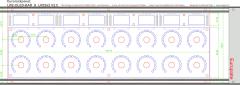
Hi dwestbury and listen202 Thanks a million for sharing this! Looks like I can finally finish my build which was stalling so far since I could not figure out how to get Fusion360 to create a proper Toolpath for the Graphics with a cheap 3018 CNC machine. I have only done simple pcb's so far with FlatCAM. I tried to follow your instructions and created a Kicad project. I did not know how to size properly so I went with Listen202's version which seems to be correctly sized. If I measure in Kicad it is (232,41 mm x 163,27 mm). I also had problems with the copper rectangles, as Kicad always complained that they should not overlap, but I hope I got it right. In Kicad itself the Silkscreen vanishes behind the copper, but if I check in GerberView it seems to be correct. If you could take a look at this project and verify that it is really ok that would be marvelous. Cheers 60/40 mb6582.zip1 point
-
@Hawkeye Thank you for the thoughtful replies. It is easy to think of future wishes and add ons but at the same time forget about how it would effect everything else. I love the Seq4+, very little I would change! And the fact that I can get into the code and try things myself is pretty amazing. That alone is a "feature" that very few seq's can boast. @flyweightIf I was looking for more humanized recordings I'd use the longer tracks with higher divisions OR the humanizer feature! Also, you can specify your own shuffle parameters, you may find something that gives you YOUR feel.. if you could analyze how your beats groove, you may just be able to create that groove as a template and there ya go. May be worth digging into. At the same time, your experience and learning from building the Seq is not lost if you sell it. You lost time, yes. I'm sure if you put it on the market it will sell pretty quickly. ~Steve1 point
-
Quick heads up on this for anyone that might wanna do this. I had some trouble compiling the above version for Linux Mint 19.3. Couple things you might need to do: ./configure --without-residfp This was giving me a weird "you need to be on a 32-bit platform at least" error (I'm on 64-bit, Ryzen) but we don't need this for outputting to an MBSID anyway The makefiles do not add -pthread. There's probably a more elegant way to fix this, but I just edited src/Makefile and added `-pthread` to the end of CFLAGS, CXXFLAGS and that seemed to avoid the errors You may need to symlink /usr/local/lib64/vice to /usr/local/lib if installing system wide (otherwise stuff like keyboard input doesn't work) You need the ROMs of course! Doing all this allowed me to bust out the HVSC intros included in the collection. Seems to work like a champ!1 point
-
Hi, Check or add the correct path in environment: Page 14 in the pdf Best Bruno1 point
-
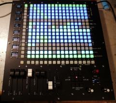
Hey people, thanks to @TK.! It's working great. Anyway I had still some flickering on the LEDs. As I stated above I left away the caps ... and this was the reason. I know have added a 10uF on the input and on the output-connector of the LED-rings and the flickering is completely eliminated! Great!! So, one core can handle a total of 10 LED (10*36=360) rings....1 point
-
Hi all, I'm finally finished my MB SEQ V4L V1 from 2011. Sorry for the poor quality. Next step for me: Learn to play Next step for my children: Raspberry PI Touchcreen extension Best regards Jack1 point
-
Hey people, in this thread I'll post time after time updates about my latest keyboard build. Also I'll use this thread to publish eagle-PCB-layout-files and schematics. But please be patient. Uploading and documenting all that stuff is highly time consuming and it's right before christmas. So far everything works great, but the work under the hood was really time consuming because I used a lot of modules... some available from Tim, some I did on my own. I think modules are great if you need high flexibility... and all the modules are working perfectly. But if it comes down to save space and wiring, modules are a mess. Anyway... here we go: So I was tired using a laptop, a soundcard, tons of cables and all that stuff on stage. So I thought: What if I put the computer into the keyboard? It was quite successful. I used an Mini-ITX mainboard from Gigabyte, an i5-3570k (I'd go with a better i7 if I hadn't had that i5 before) with a low profile cooler. The mainboard is equipped with 16GB of RAM. Also I integrated two Samsung SSDs with 500GB each. The whole thing is powered through a Seasonic SS250U power supply. As soundcard I use a PCIe card from RME HDSPe AiO. Because this only has two audio in/outs, I also bought two expansion-board that gives me another four in and outs. The first two analog-outs are going through a self-made DI-box with high quality LEHLE-transformer... absolutely great stuff. This DI-box features also a 20dB PAD and a GND-lift. Let's hand over to the MIDIbox-side: I use two cores. One of them only takes care of the keyboard scanning. It was very important to me to not make a compromise on this. This core is connected via MIDI-out to the MIDI-In of the other core. Both cores are STM32F4 based. I used my own PCBs for that. @TK. Is it a problem if I publish those schematics and layouts for the core? I know that the official core is not published yet to cover the costs for PCB production and development. The PCB I developed only contains the connectors I need: it has J8/9, J19, J10A, J11 and J30 (as far as I remember... don't have it right in front of me at the moment). I tried to get a smaller footprint of the whole PCB. It also features a MicroSD-card slot instead of the SD-card-slot in the official PCB. My keyboard has nine analog faders build in... they are not motorized. I don't need that for now as they are much more expensive and also take more space. Also they are more difficult to wire up and connect. At first I did some tests with the AINSER8. But after a while I gave AINSER64 a try with the result, that it has less jitter than the AINSER8. The faders are a lot more quiet than with AINSER8. As I needed more than 16 analog inputs this was needed anyway. I power the AINSER64 through the core and the core receives it's power directly from the seasonic-power supply and NOT via USB. I needed some LEDs to visualize the status of my faders. A long long time ago I wanted to start another LED-fader-project but never finished it. So I had a lot of those LED-bars laying around... I took them and putted them into the board... works and feels great! On the next revision I'd try to use one big PCB for all 9 LED-bars to safe wiring and time for mounting. Now I used two 10pin IDC connectors (with only 8 pins of each are connected to the LED-bars = 16 LEDs). I did some mistakes when assembling the LED-PCBs... now sometimes some LEDs don't work... anyway... I can live with that for now. @TK. How about the WS2812 or APA102-LEDs? Do you think it's worth using them as LED-rings? I'm not sure what the status is and if they are supported in that way by MIDIbox. Would be a great alternative but they take a lot more space than 0603 SMD LEDs of course. The LED-bars are connected to small modules I did based on @novski designs. Those small modules are equipped with one or two DIN / DOUT modules. They work great and the advantage is, that I can stack them directly on the pinheader of the PCB... no cables needed! A bit hotglue and you are ready to go. I also have 8 encoders on each side of the keyboard. The right side is not connected yet... not sure if I do need so many encoders ;-) Of course they are also equipped with LED-rings. While the LED-bars where assembled by factory (I think I used SEEED) the encoder-rings came blank... so it took me a looooooong time adding 128 0805 SMD LEDs to all PCBs... at this time I had not have my reflow-oven... with this one that might be an easy task :-) The encoders (and the switches of the encoders) are connected to a 4xDIN board from novski. I'm not sure if this board really works well. Sometimes if I set debug on, MIOS lists tons of EVENT_BUTTONS. I'll need to investigate that. Maybe it has something to do with RC1 / RC2 lines. Underneath the faders I have a set of 2x8 buttons. I'm not really happy with them. I did the caps by myself and this was a really shitty work... next time I will use tact-switches that already come with caps f.e. TC011 like I did in the 1x8 button-row right in front of the player / underneath the display. For the buttons I designed a DIO-breakout-board. This breakout-board splits the matrix configuration of the 2x8 pinheader of the DIO-module to a more usable 2x5pin header-configuration with the row on pin 1 and the switch-lines on 3-10. With this way it's very easy to connect tons of buttons to a MIDIbox. . Same for the LEDs of the buttons. I used a DOUT-module with ULN2803 as LED driver (btw. I drive all LEDs with ULN2803 and do NOT use a resistor before or after the LEDs. As those LED-lines are scanned, a limiting resistor doesn't seem to be necessary). That's mainly it... the keyboard has two MIDI I/Os on the back as well as four pedal connectors for two switches and two expression pedals. The touchscreen in the middle is a 10" capacitive screen... that works awesome!! That's the story for now... like I said I'll try to keep this thread alive and add the PCB layouts and schematics later on. Thanks for reading!! Best, Chris1 point
-
Hi everyone ! I experienced the same problem, and The Ancient One's solution works perfectly for me. I changed the 220R resistors to 68R for R21 and R22. Now the 9090 detects the signal without any issue. Thank you a lot Michael ! Théo1 point
-
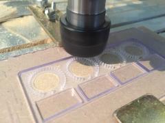
From the album: OLRE16
Drilling ring and oled window in PMMA1 point -
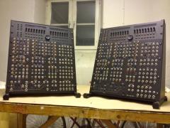
From the album: Jojjelito's pixx-o-stuff
The woodwork part of the case is done. After getting clad with black foil the new working name was temporarily set to Black Satan. Darth Vader stopped by for a cup of tea and wanted one.© Johan T
1 point