Leaderboard


Popular Content
Showing content with the highest reputation since 10/22/2009 in Blog Entries
-
The Sequencer is finally up an running in his new Acrylic case ... Todo's ... adding a 5 Volt external PS for the STM32F4 instead of USB-cable and building the Frontpanel for the Line-Driverstuff4 points
-
I`m back after long time out of MB community and doing electronics in general. I have quite a few unfinished projects that needs some attention. In most cases it is just building housings and final touches, but still a lot of work. I feel bit rusty now, but I`ll catch what I`ve missed. See you around! ;)4 points
-
MIDIbox has been a big deal to me, for a long time. While I’ve built a few MIDIbox projects over the years, I always wanted to be a bigger contributor, and there has always been something in my life to stop me. Over the past few years my marriage has taken a big shit all over my life. I find myself with great ideas, only unable to fully realize them because of the amount of trouble in my life, particularly because I just couldn’t seem to get along with my wife. I am not suggesting for a moment that MIDIboxing should be more important to anybody than the sacred institution of marriage, but … sometimes people will find that their creative life is being stifled by forces like an ill-chosen partner. Such is the case with me. I don’t want to go too far into the gorey details here., other than to say that I have been very hot and cold with the MIDIbox community for the past 4 years or so. What I have done has been with the very best of intentions: I have organized multiple bulk orders and I have contributed interesting designs and ideas. But it is difficult to properly see these things to full fruition when your emotions are forever being tugged by external forces. I’m telling you now, with mixed emotions, that about two months ago my wife and I finally separated. While this is a sad time in my life for obvious reasons, it is also very liberating. Finally I can tell the truth: the reason why I was often hard to reach, and I was sometimes (very) late in delivering on stuff that I promised, is that I have been completely consumed by marital breakdown. Sometimes it took me a very long time to ship things like knobs, after having made deals in good faith. While I have long since straightened everything around with everybody who may have ever had issues, I never really offered any good explanation other than “personal issuesâ€. Well today I am glad to announce freely that I have no more personal issues. I finally left her about 2 months ago, and I am no longer looking back. It will still take a bit longer before I achieve the participation level I always wanted with the MIDIbox community, and my own DIY projects, I am finally able to breathe a sigh of relief. I will finally have the time to devote to these things without judgement or undue punishment. I really don’t want to sound like I have chosen MIDIbox over marriage. Rather, I have chosen not to be unreasonably judged with no basis or standards, by an individual with no right to do so. This encompasses not only my “Synth DIY†activities, but also the artistic rationale that allows me to freely create. Without trying to explain everything that has gone wrong in my life, I am offering a sincere apology to all those who unnecessarily waited months for a few knobs, and to those who have received my (attemptedly constructive) critiques on their concepts and designs without detailed followups. I have lots to offer this amazing community, and I am saddened that the value of my verbage has been continuously compromised by my scarcity. Little by little I will be returning in the months to come. Once I get my new home and new workshop in order, I hope to be able to participate with more regularity and loyalty than I ever have. In other news, my stage name is no longer “nebulaâ€. I have recently been working with a Canadian label who will be releasing some of my music under my actual given name: Steve Cowan. I’ll keep nebula for forums and maybe later as a musical alter-ego, but I’m excited to finally have an opportunity to get my music out to a larger audience, under any name. (FYI: when I join forums and find that “nebula†is already taken, I’ve been registering as “infindebulaâ€.) I have also started a blog site to publicize the efforts of myself and other nearby artists. Have a look at juggernautmusic.com to see what we’ve been up to. The site is active now, but will officially “launch†sometime over the next few months. Thanks for listening, my fellow MIDIboxers. I’ve always enjoyed being a part of this community, and I can’t wait to play a bigger part in the years to come.3 points
-
When interfacing a Joystick, Modwheel or Pitchbender it is sometimes found that the voltage range on the potentiometer output is well inside the range of the Core ADC input. This can often be overcome with digital calibration in the firmware (e.g MIDIbox KB) in some cases there is extreme loss of resolution. Presented here is a circuit to overcome this to give the ADC the full range (in this case 0..3.3V) even though the range of the potentiometer is well inside this. The design process is very easily done following this app note:sloa097.pdf 230.01K 12 downloads I've done a spreadsheet to make it even easier!Scale Offset.zip 2.45K 9 downloads If you don't have MS Excel, you can use it with free tools Google Docs, or Open Office. To use the speadsheet you enter numbers into the blue fields. The input range at the top as measured on your pot. In preparing the examples, I played with the value of Rg2 so that Rg2+R1 came close to 10k. This allowed to replace them with a 10k trimpot as in the example circuits. It was just as well, as the trimpot did require some tweaking away from the calculated values, I found. I chose LM324 op amp as it's output goes down very close to 0V. It's maximum possible output with a Vcc=5V is about 3.5V which should be quite safe with a 3.3V Core ADC such as LPC17 MBHP Core. There are 4 op amps in this device, so 4 scaling/offset circuits can be implemented with 1 chip. Here's the circuit with 2 worked examples: Here's the test (input on left, output on right) showing 3 points (Modwheel example): Here's another test (input on left, output on right) showing 3 points (Pitchbender example):2 points
-
midiboxng2 points
-
CORE_STM32F4 done .. it does blink, hope it works too2 points
-
The missing socket arrived this morning. Full of will power I waited until after the days work was done before getting out the now rapidly declining box of bits. Socket in, C64 PSU tested, 9V tested good, so was ready to go. Small glitch until I realised that I had to change the core ID in MIOS Studio too, then all loaded smoothly. Fitted the 6852's one pair at a time, and ran through the sound banks, with a silly grin just getting wider on my face. Still got a minor bit of front panel work to do, (3 spacers came unglued), and a little bit of fault tracing - the mix out doesn't seem to be working, but all is good, and the only last bits I need are 4 knobs for the feedback pots. Now a lot of reading and learning to do. This thing is a small cased sound mainframe and I want to be able to drive it as it deserves.. Love the way my Korg Kontrol 49 keyboard loops up to a lot of the front panel controls too. So very grateful to TK and Wilba for this.2 points
-
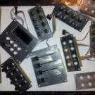
Nach nem sehr chaotischen Jahr wurde die Projektkiste ausgepackt und eine Bestandsaufnahme gemacht. Das Projekt ist inzwischen mehr als 2 Jahre alt aber das ist nach wie vor die Zielsetzung: 3 Sektionen + 2 Extra Encoder (dafür fehlen noch entsprechende Alustücke und die Bohrungen in der Aluplattte 1. Sektion 16 Potis , 14 Taster , 14 Leds Stand : Front fertig lackiert, Teile montiert, 2. Sektion 2 Potis , 11 Leds , 5 Encoder Stand : Aluplatte fertig, Teile montiert - fehlt noch die Folie 3. Sektion 4 Fader , 4 Encoder, 2 Leds Stand : es fehlt noch die Aluplatte mit den Faderschlitzen und Potilöchern To DO: Besorgungen: farbige IC-Sockel 18 Pin 4 Stück (vorzugsweise Rot oder Blau) farbige IC-Sockel 16 Pin 12 Stück (je 4 gelb, grün,blau oder rot) 10 Pin Header 14 Stück Pinheader in grün (bei Ebay gefunden) 4 Quarze 20 MHz für I2C 12 Kondensator für i2C Platine für D-In D-out und An-In Ceramic Cap 100 nF 16 Ceramic Cap 15 pF 8 Polarised Capacitor 10 uF 6 - Aluplatte für Fader und Encoder besorgen/anfertigen - Folie Laminieen für Sek.2 - Sek 1 verkabeln - Ultracore zu Ende löten - Pics brennen2 points
-
Construction d'un séquenceur, SEQ V4 midibox (2016) http://ksir-diy.blogspot.fr/ Après la construction de 2 contrôleurs midi le modulebox et le pushbox, je décide de fabriquer un séquenceur. Toutes les infos proviennent du site: Merci T.K. http://www.ucapps.de/midibox_seq.html 1ere étape, construction de la BOM, liste des pièces a commander https://docs.google.com/spreadsheets/d/1QeJV0jgEi0ly2ljBv7idEdsqg11bE0XkwrLQFL_UkEw/edit?usp=sharing En attendant la réception des circuits imprimés que j'ai commandé sur : http://midiboxshop.bigcartel.com/ J'essaye de créer moi même ces circuits imprimés sur kicad: https://drive.google.com/file/d/0B0X-WnBiV-XXdldpQXRjWWpOcGM/view?usp=sharing . après la schématique le routage: import et commande chez https://easyeda.com/fr Le 05 juillet 2016 commande de composants effectuée chez mouser et reichelt selon la BOM suivante : https://drive.google.com/file/d/0B0X-WnBiV-XXVzUzRnEtZXBOZjQ/view?usp=sharing Le 18 septembre 2016 Réception des circuits imprimés du CORE stm32f4 que j'ai redessinés précédemment et fais fabriqués par https://easyeda.com/fr Peuplage d'un PCB 1er Test :) youpi ça s'allume : La face avant wilba n'étant disponible en vente sur aucun site, je décide de la redessiner sur kicad et c'est reparti pour une schématique : routage: envoi pour commande à https://easyeda.com/fr prévisualisation avec blender 2 octobre 2016 ; Commande de PCBs reçue , Et c'est parti pour la soudure :) assemblage et test fabrication de la boite1 point
-
Nothing earth shatteringly different from the normal happening yet. I've just got my (very lovely) boards delivered from SmashTV and soldered them up, so here sit two STM32F4 cores (sans SD card hardware because it's not here yet)1 point
-
The SIL couldn't be delivered and I had to do the LED twice because of the round buttons, but progress is visible :)1 point
-
Not much time this weekend But I managed to Solder up a few NEW DIN/DOUT boards. And the complication comes in the pinning of the new boards, the arrangement of the 2x5 header does not allow me to use my old 1x5 cables to the CS as wired in V3, due to the arrangement of the SR inputs. Not a big deal, off to the HW config file to do some editing (It was bound to happen sooner or later!)..... Other observations on the New DIN/DOUT boards....It would be nice to have a bit more clearance to use shrouded (Box) headers, The I/O headers on the end overlap board mounting holes and the SR connections would have been too close on one of the boards IIRC. No big deal, I used the srouded headers on the SRIO chain, and normal ones on the I/O pins.1 point
-
So many years ago I started an MBSEQv3. Life happened, moved a couple times, it sat on a shelf unfinished. So now I begin to upgrade it to v4 and finish it off. below are some pics of it after pulling it off the shelf: The case is an old rackmount Altec Lansing Mixer, I will have a new panel laser cut from acrylic You can see the 4x16 BLM's i started, one is finished the other I forgot to stuff diodes.....(they were made months apart) DOH! board on the right with the cutout in the middle is the transport section, a large jog wheel will go with the encoder shaft through the cutout. above it you can see the old MIOS8 Core. not shown are the DIN's and DOUT's. I've got a NEW MIOS32 core(STM32F4) built and testing now. Looks like the pinning of the LCD is different now so a little work there. I'll finish the Veroboard mockups to see how I like the handling and layout before commiting to having some PCB's made. I've thought about using the WILBA panel but I really want a custom solution and love the look of the SCHADOW switches I have. I have a large quantity of them but they are pulls, I hope reliability doesnt bite me in the end though they are extremely long life switches. The caps are the type that I can print my own labels and put under the clear cap. There will be a bit of free panel space and some room in the case, I am debating what to do with it. Integrate a SID, FM, or GOOM Synth? Some dedicated MBNG controls (from a second Core) Maybe some eurorack rails will fit? Just thought of that will have to see if theres enough room? I'm open to suggestions. I like the case, it fits nicely in an empty rack space I have, and is about the size of my yamaha RS7000, but will have more controls I think. I like controls.... ;) Let me know what Ideas you might have for the extra space !1 point
-
Hy! My name is Nicolas, and I'll try to translate an already posted message in french. Im passionated on MIDI technologies since I was a little boy, even if I understood later that i could'nt connect my joystick to dads minimoog ;) Now Im looking to develop a touchscreen interface to manage different hardware equipments, so I need some peace of information to go forward on this: As Im rather good on Macromedia Flash: where do you think I can find information on how to communicate via MIDI protocols? But I'm a really bad electronician: so how can i find info on to integrate to fantastic uCApps interfaces touch screen capabilities? next points to come. Thank you for your comments! See you very soon, Nicolas *1 point
-
Hello everybody much time hast past since my last entry here, but this project is not dead. what happened in the meantime? my studies ate up much more time than I planned, so I had to change priorities. but its not all about math and machine construction ;-) first step was creating all the pcbs i need for building the controller and - my very own PIC-Burner. I used his lovely little pre-project to gain some advanced skills for the etching machine at work. thanks to my boss, i got a nice box, LEDs and faceplate for it. next step was the first big order from bürklin (having access to non privat selling companies via the company i work for in my freetime is a big advantage here). the order contained all parts for building core module, several dins, ains and douts, and a blue display from pollin. due to my own impatience, all modules were finished very fast, but I made a mistake on the interconnection between core and Display. result was a broken PIC and core... damnit. I borrowed 2 other displays from a friend of mine and ordered a new pic. this time, everything went well and I got the core up and running, with 128_din_dout software. Another sunday evening solder marathon later, my very first prototype with one din and ain module 4 switches, three pots and one rotary switch (for multilayering knobs in the software) was build and running. First tests with traktor pro 1.2 were sucessfull. At this point, the progress of my project begun to slown down. main reason for that was to find a reseller for my special alps potentiometers with buildin switches. actual status is that I am waiting for two mails from different resellers which I ve asked. also, finding round aluminium profiles for the boxing (I have to have round corners on it!) was a tough job. I spend around 3 weeks on the internet until I found www.weloe.com. I ordered 12 8cm pieces for three boxes (yes I am going to build more xD) and awaited them in january. it was a big surprise when they arrived this week just at my birthday xD rest of the time I spent on this project I thought a lot about the frontplate and the layout of its buttons. the picture from the last entry is not actual anymore, but I made only minor changes. I think the frontplate will be the last thing that i order, since there are many things that still have to be planned in detail, for example the display (I want to integrate a graphic one for informations like songtitle, bpm and selected effect, but i still did not figure out if mios support anything like that). two other big problems i have to solve are the mounting of the pots and the control- system for my RGB LEDs. so long Nasrudin1 point


.jpg.55c3fe54131031c715cb0a6a9b9fa3e8.thumb.jpg.868582cb21d263da288659a773d820db.jpg)