

FantomXR
-
Posts
1,035 -
Joined
-
Last visited
-
Days Won
22
Content Type
Profiles
Forums
Blogs
Gallery
Posts posted by FantomXR
-
-
Great!
I drawed a schematic. But I think I need to sit right in front of the LEDs to know, where which wire to solder ;) But all orders were done today. I should get a few nice packages the next days.I forgot to mention: I have some PCBs with a led ring on it. Its 0603 warmwhite SMD LEDs. How to connect them to the two DOUTs? Is that possible or do I need a dedicated DOUT for those LEDs? If I connect them all to one color-SR there shouldn't be a problem, right?
-
Cooles Projekt!
Du hast mich da noch auf eine andere und viel einfachere Idee gebracht.Als Keyboarder kann man ja bekanntlicherweise nie genug Sounds gleichzeitig abfeuern. Hände sind auf den Tasten... da kam mir die Idee, eine Art "Fuß-Pad" zu bauen. Der Fuß macht sowieso die ganze Zeit den Takt mit. Für Claps, Snares oder Bassdrums natürlich wie geschaffen.
Könnte ich dafür einen solchen FSR benutzen? Und sollte man dann tatsächlich einen Schmitt-Trigger davor setzen oder erledigt das die Firmware des MBNG von selbst?
Auch mach ich mir Gedanken wegen des Gewichts. Zwar stemme ich nicht mein komplettes Gewicht auf den Sensor (ich sitze beim Spielen meistens), aber der Fuß an sich und die Kraft, mit der der Fuß im Takt mit macht, ist sicherlich höher als 10kg. Käme wohl auf einen Versuch drauf an. Wenn man den Sensor zwischen zwei Schaumstoffplatten steckt, könnte das funktionieren.
-
Yes!
I draw a diagram in Eagle to make it clear.Because I need to use a second DOUT anyway, the first matrix will be 6x8 (six RGB LEDs in eight rows). Did I get it right, that the first SR sets the rows. On the second SR I need to connect all red LEDs (which would be six lines, each with 8 LEDs), third SR all green, 4th SR all blue.
Cause your schematic in this topic
says something else.
-
Thanks!
I read thru the thread. Interesting stuff out there! ;)I want to use ULN2803 drivers anyway to drive the LEDs. I hope, I don't need to setup a 16x4 instead of 8x8 to get good brightness levels.
I think I need to hook up some kind of schematic to not get confused by all the connections ;)
Anyway: If I want to use more than 64 RGB LEDs it's necessary to use a second DOUTx4 or it's possible to enhance it to a 10x8 matrix?
-
I'm trying to understand, what would be the easiest way to connect around 70 RGB LEDs (so around 210 single LEDs). I took a look into the NG-manual. In the DOUT-Matrix chapter it says:
"These parameters allow to drive duo-colour or RGB LEDs by using a second set of DOUTs connected to the green LEDs."
and
"These parameters allow to drive RGB LEDs by using a third set of DOUTs connected to the blue LEDs."
Do I really need to setup one DOUT (not shift register) per color? If didn't make a mistake in my calculation, one DOUT would be enough to drive 70 RGB LEDs in matrix-mode. I thought, I could connect the LEDs like this:
LED1:
Red = D7
Green = D6
Blue = D5
LED2:
Red = D4Green = D3
Blue = D2etc.
-
Thanks! I found it.
Another idea comes to my mind when I remember this nice ableton controller which is here in the forum. He put acryl on the switches and illuminated them, which looks very nice. I don't need RGB LEDs, so this might be not too difficult. I just need some tact switches with a flat head.
Thanks for your replies.
-
Yes, maybe I should really do it that way.
Do you have the part numbers of the switch and the fitting cap? Mousers / Digikey is really big ;)
-
No schematic right now. And it was not planed to draw one.
Maybe I should draw a sketch. :)
-
Hey,
for my faderbox project I'm looking for tact switches, which can be snap in or panel mounted.
I don't want to create or use PCBs for the switches.
I can't find anything on the web.
Any suggestions?
thanks,
Chris
-
Hey,
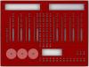
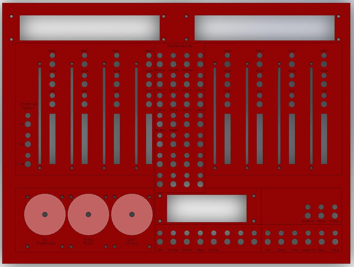
I've read a lot in this forum and ucapps and I'm ready to build my faderbox.
See attachement for pic.
Here is the idea:
Eight motorfaders which banks can be switched by pressing one of the "fader-mode" buttons. Each button on this controller has a led to visualize the actual status. Each motorfader has a select, mute and solo button and a led-meter too. On the left side the tracks can be switched so I can access in this case up to 24 tracks.Above the faders are 2x40 LCDs. Every fader has 2x4 chars, one is empty to the left, one to the right.
At the bottom there are encoders. I already made a pcb for them so led rings will be there too. Because I used SMD LEDs on the PCB, the idea is to cut the material (in this case 4mm aluminium) 2mm deep and glue a fitting piece of acryl into this hole.
The encoder-mode can also be switched by the buttons to the right.
I also added some transport buttons and three "misc" buttons.
Next to the encoder is a 2x20 LCD which should show the actual setting of the encoders in db / ratio / hz / whatever.
As fas as I didn't make a mistake calculating the parts, I need the following:
- 1x LPC1769 Core
- 1x MF_NG
- 2x DOUT (it's 216LEDs in total)
- 1x DIO (it's 75 buttons in total)
Now: Did I overlooked something or is everything fine and I can start, placing the orders? ;)
Would be great to hear / read from you.
Thanks,
Chris
-
And they have some nice oleds too. I'm expecting, that they are working with midibox? http://www.buy-display.com/default/oled-display-module.html There is no breakout board. So a bit of soldering is necessary, but they are nice and cheap... Are there any problems with that?
-
Im USB-Bereich gibt es Repeater für recht wenig Geld.
Bei MIDI ist meiner Meinung auch nach 15m Schluss bzw. es entsteht die Gefahr, dass nicht mehr alle Daten durchkommen...
-
Hey,
I'm wondering, if there is a 2x8 display with backlight integrated.
I'm thinking about having a lcd under each encoder. So, 2x8 would be a nice size for that.
Otherweise I need to buy bigger displays and combine several controllers on the display.
Thanks,
Chris -
Maybe you can use the Dim-command. Take a look at the ng-manual.
-
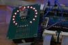
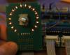
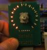
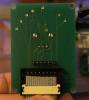
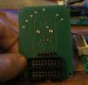
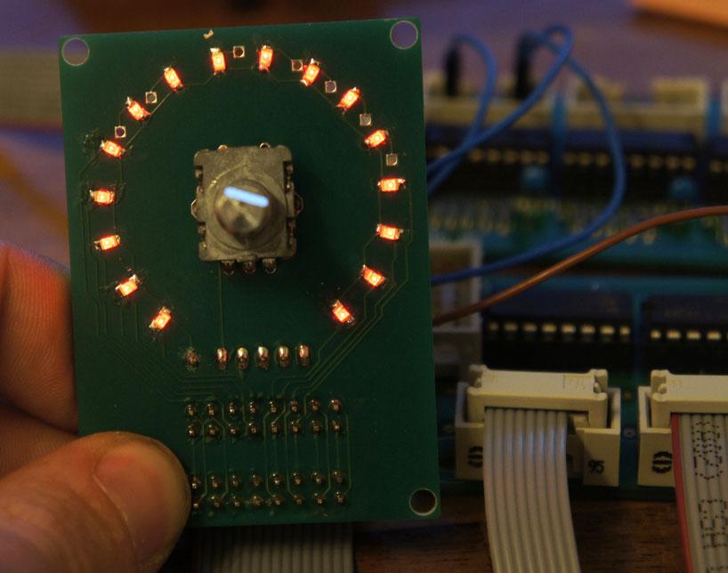
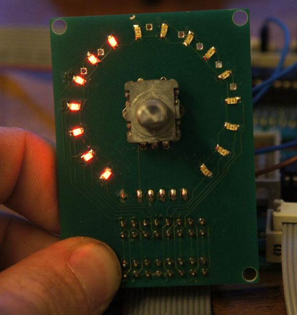
For those of you, who don't want to use 2x8 encoders at a time, here is the first design of a PCB I made. There are a few things to improve, but it's working!
In the next days I will equip another PCB with the parts and see, if the forwarding is working and if there is enough space for all the connectors / connections.
For now the LEDs are driven by the 74H595 only and each LED is feeded with 15mA. I think, for later use they are not bright enough. I don't think, things will change, if I use a ULN2803 for driving the LEDs, because the difference in brightness between 15mA or 20mA is really not that much. Maybe I should use other LEDs...
-
Hast du einen link zu den Buttons, die du verwendest?
-
I thought, if I use 8 faders which are all the same, than I can put the same values on every fader.
But I will try that. What PWM setting do you recommend?
I already updated to 1.004.
-
Thanks tk! Your configuration is working! Nice!
But there is one fader, that is moving slower than all the others and another fader makes trouble and is very loud. Its moving down perfect, but up it stucks after a few cm. I think I need to check the connections again.
And another thing comes up: If I use the bank buttons, sometimes one or more fader is / are not moving to its other position. It sticks were it is. This happens randomly on all faders....
Maybe I should build another MF board. I'm not sure, if it's really working like it should.
-
Thanks Thorsten!
-
Hey,
I need some help with my configuration-file.
I try to change the CC which is send by a motorfader via the MF_NG module. Here is my file:
# Reset to default
RESET_HW
# MOTORFADERMODUL
MF n=1 enabled=1 midi_in_port=IN1 midi_out_port=OUT1 config_port=USB2 chn=1
# EVENTs
EVENT_BUTTON id=101 meta=SetBank range=1:1 button_mode=OnOnly
EVENT_BUTTON id=102 meta=SetBank range=1:2 button_mode=OnOnly
EVENT_MF id=3 hw_id=1 fwd_to_lcd=1 type=CC chn= 1 cc= 118 bank=1
EVENT_MF id=4 hw_id=1 fwd_to_lcd=1 type=CC chn= 1 cc= 120 bank=2I have two buttons connected to a DIN at pin D0 and D1. I know, that they are working, because if I assign CCs to them, the monitor in MIOS is showing them to me.
But here nothing happens. It doesn't matter if I press a button or not. The fader is still sending CC# 118.
The MF_NG is working in Motormix Emulation - Mode.
Is it part of the emulation, that the fader is sending CC# 0 and CC# 32 besides the CC I define in the NGC?
Thanks in advance!
-
How much do you ask for it?
-
Exactly - I will test this on my Stribe (and I can post a schematic once the DOUT_MATRIX driver has been enhanced :))
Btw.: the DIN/DOUT_MATRIX should already work with your "MBSEQ 16x4 BLM board", because it supports rows=4 mode
Best Regards, Thorsten.
I'm looking forward to see the schematic ;)
Stribe is still a nice project!!
-
Why is the midibox limited to eight displays? I would love to have a ninth :)
-
Its from eBay. I will send you the link in a minute.
The seller says, it's alps EC11.


WANTED DOUT & PIC18F452 (for MF_NG)
in Fleamarket
Posted
Hey,
nothing more to say.
Looking for someone in Germany, who has a DOUT-Modul (best from SmashTV) and / or a PIC, which is bootloader-programmed, for sale. Mike has no PICs at the moment and will be on holiday till 1st of July.
Thanks,
Chris