

novski
-
Posts
460 -
Joined
-
Last visited
-
Days Won
5
Content Type
Profiles
Forums
Blogs
Gallery
Everything posted by novski
-
Hi FantomXR in the Manual: http://ucapps.de/midibox_ng_manual_ngc.html dimmed=<0 or 1> LEDs can now be dimmed with 16 brightness levels over the value range. This feature has to be enabled with dimmed=1 in the EVENT_* definition. Configuration example: cfg/test/dimled.ngc. LEDs in a matrix configuration can be dimmed as well. The dim range is the same (0..15), but the effective dim level is limited by the number of scanned rows: 4 rows: only 8 levels (0..1, 2..3, 4..5, 6..7, 8..9, 10..11, 12..13, 14..15) 8 rows: only 4 levels (0..3, 4..7, 8..11, 12..15) 16 rows: only 2 levels (0..7, 8..15) Configuration example: cfg/test/dimled_m.ngc. Best Regards Novski
-
 Verry appreciated! Thank you!
 -
No. NG doesn't have a Midi Player/Recorder... You can read more about here: ucapps.de
-
Well thats sad. Midibox is a extremely cool Project. If you like to do things your self with midi or related, im sure it will make you happy. But it isn't a "unboxing-and-ready-to-use thing". If you don't get it done with that different product, you may come back and get a new pic from the midibox-shop.com for further tests. Best regards Novski
-
hmm i can't follow. I think more to my english than what you wrote. Yes to your Question about the Device ID on the Chip. There must be one. Do i unterstand you right, that what ever you do, it confirms with "the application is up and running." ??? Did you connect the Core to the USB interface direct or is there a joystick in between? First of all: Connect it directly for Testing and use the M-Audio one because its really a problem that those cheap ones don't work. (they can work for some Midi Audio applications but not for the sysex loading part of MIOS...) I think you have to click trough the ID numbers and take the time it needs because the next step is difficult: There is a ID changer in ucapps.de LINK but read the manual in the .zip i have never used it until now. hoppe that im not telling you bullsh.. :-) Maybe someone can confirm those steps or has an idea...??? best regards novski
-
Hey Jazza! The Controller Microchip should have a ID number. Is there a sticker on top of it that has handwriten numbers on top of zeros? Because that wold be the Hex number of your ID witch you have to convert to Decimal and write it in to the ID box in Mios Studio. Second question is about what you wrote: " Plugged in my £3 Amazon special USB-MIDI adaptor and got MIDI output." Does that mean you received midi from the organ? Best regards Novski
-
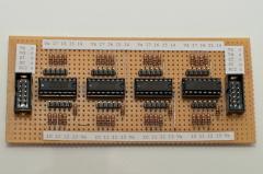
Nice! i also did the hole thing in a similar way once. But unfourtunately i didn't get so far to test it completely until now. Im currently making my page new. After that i will be able to provide all designs as Eagle file an lib... as opensource. Just give me a month or two... If anybody is interested in beta-testing i have a spare unequiped pcb (foto) to give away.
-
http://www.midibox.org/dokuwiki/doku.php?id=midi_interface_whitelist
-
Cheapest place for Alps motorised faders? Any interest in a group buy?
novski replied to DubplateDerek's topic in Bulk Orders
I have spare. -
@sneakthief; wold you share the schematic of that MIDI I/O board?
-
Regarding the brightness if the LEDs there is a way to stuff a ULN2803 to the DOUT Board from SmashTV TO make the current consistent. This is not exact your Need but quite near... http://www.ucapps.de/midio128/relay_example.pdf br Novski
-
Hi ibaman555 Sounds like a great NG project that you are starting! Im just not so shure what a analog VU that is converted from Digital brings on advatage... The attack time will be delayed even more and the AOUT will defenetly smothen the small steps in between but this may not satisfy as you whant because the precisenes of the meter will be related to the digital steps that are sent from your DAW... With midi thats normaly (please correct me if im wrong...) i think 8bit. Even trough it will defenetly look great! For the possability you need to ask TK. If the Matrix Metering is already prepared... Best regards Novski
-
I just realised that your layout is actualy single side compatible! Pin 4 cold go outside of pin 2 on toplayer. As well as pin 14 wich is possible to route on top to the SIL! Wolnderful. You may save some money like that... If you have time its helpful to have lables on the bottom side in case of issues... br Novski
-
Yes, the store will get a update as soon as i get some spare time. Im not so happy with the posabillites of it right now. The silk-screen of the DIL Header is on that side it should be fitted. It has to be soldered first anyway and i will make a assembly instruction for that online someday... br Novski
-
Well i just needed it like that...
-
I did the same. Made some more for those that don't know how to make a pcb. They are available in link below, as well...
-
Cheapest place for Alps motorised faders? Any interest in a group buy?
novski replied to DubplateDerek's topic in Bulk Orders
Were do you live? -
 nice!
nice! -
Hi i always forget how it works within a month. :rolleyes: I didn't configure anything in .ngc file... After some tests i also remembered to chose the right config port from the drop down and set the query... puh. so much values to think of. Some day i will have to wright a tutorial in to the wiki... thanks TK.
-
There are diferences on the schematic of STM32F4Discovery! J10A/B show different labels then the arrows out of the Discovery uC pins. J10A D0 => PE8 D0 - correct J10A D1 => PE9 D2 J10A D2 => PE10 D1 J10A D3 => PE11 D4 J10A D4 => PE12 D3 seams like something swapped all odd to all even numbers on ether J10 or uC side... Hope you didn't make a mistake with the new core pcb! I'm looking forward to get it... :smile: best regards novski
-
HI I have problems contacting a MF_NG core i have made custom. Because i coldn't find out whats wrong i left out all Optocupler parts and connected LPC17-MO1 to MF_NG-MI directly. I even measure a short contact between P2.0 and Pin26 but still MIOS doesn't connect to the MF_NG, alltrough its LED Status is pulsing. Now im not sure about the midi router... (sorry, i always get confused with that) If i upload midibox_NG_1.029 to my LPC17 is it automaticaly prepared to connect over Midi 1 to a MF_NG or does it need a routing setting? best regards novski
-
Ok. Thank you TK.
-
Thanks for that! Its close but does not fit for my 24 oleds.... Seams to be not implemented jet... Il stick to LPC17... Best regards Novski
-
Does nobody, have a idea how to connect J28? Thanks for help! Best regards Novski
-
Hi, i have problems understanding how to connect my 24 OLEDs. I can't find J28 on the schematic and also no infos on ucapps... I know the doku is not ready yet but... :rolleyes: Thanks Novski
