

geth
-
Posts
25 -
Joined
-
Last visited
Content Type
Profiles
Forums
Blogs
Gallery
Everything posted by geth
-
-
-
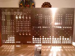
From the album: Mothership Midi-Controller
-
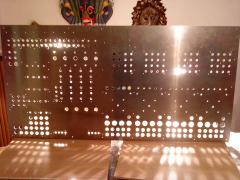
From the album: Mothership Midi-Controller
-
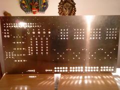
From the album: Mothership Midi-Controller
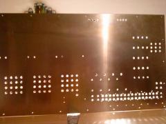
Panel is now not turned upside down anymore (still the view of the backside, because it looks better without the paper). -
From the album: Mothership Midi-Controller
-
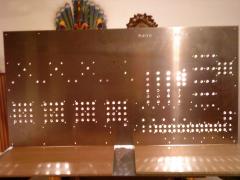
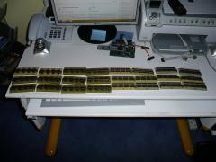
From the album: Mothership Midi-Controller
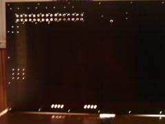
Panel is turned upside down. -
From the album: Mothership Midi-Controller
-
From the album: Mothership Midi-Controller
As a Schaeffer-frontpanel would be to expensive and it did not work out to make the panel on a CNC-mill with the connections of a friend, I decided to drill the panel myself.<br /><br />PS: My camera broke, the frontpanel-pics are made with my mobile phone, so sorry for the quality. -
From the album: Mothership Midi-Controller
-
From the album: Mothership Midi-Controller
-
getting closer: LCD installation a success!
geth commented on Blatboy's blog entry in Blatboy's Blog
Congrats! -
Nice layout! Do you order it from Schäfer-Frontplatten?
-
Hi! Today I got my membrane-Potentiometers (100mm-Hotpot) from Watterott. I had to wire a 10k resitor to between the "wiper" and ground. If this is not done, when the membrane is not touched it, and therefore the AD-converter-input, doesn't have any scecified contact with ground or 3.3V so it will send random signals, which cannot be filtered. With the 10k resitor, the value will be zero when the membrane is not touched, but this can easily be filtered by software. Like this the pot works quite well, no jittering. I have a round one and 8 linear potentiometers. I also got pressure sensitive resitors (sadly I did not manage an own post for it, I was rahter busy). Very simple wireing, just the pressure sensitive resitor between 3.3V and the AD-input and a 10k resitor between the input and ground. This works quite good and is fun to press =). I also got my 100 mini-arcade-buttons, yeah! Greetings geth
-
Hi, I found some time to check the sensor again. So my current wireing is like this: 5+ Volt and ground from the sensor to J2 with a 100nF cap between them. And the sensor output to an Ain frome the core, with another 100nF cap between this and ground. Now the input is jittering, but this comes from the sensor, if I put my finger over the photodiode of the sensor, the jittering stops and the output drops to zero. The infrared LED seems to be very strong, because if I put my finger (directly) over the photodiode and the LED, the output has still one fourth of its maximum value. So I will definetly use an additional switch to toggle this sensor on and of (otherwise mapping in traktor would be a pain), and recommend this to everyone else using this sensor. Greetings Geth
-
Yeah, after evenings of soldering ist done! I'm still a bit unsure whether I should have done some of them on vectorboard, but like this, I can attach my modules directly under each button-cluster. Greetings Geth
-
hi, just a short update: Concerning the jittering: When I played around today I found out that the jittering is greater (probably like an unused open pot) without the 100nF capacitor on the connection of the yellow and the grey wire, I guess I was to tiered for proper testing... With this cap solderd back the jittering is gone again, but when I wait long enough it comes again, I suppose this is because the otherside is not connected to ground, I will test that when I have more time. Thanks for the replies, I totally forgot to check the outputvoltages :frantics: . I will definitly go for the software-correction of the 5%-problem in the custom code of my controller, so thanks for your clear instructions. By the way, it seems intelligent to me to add a switch to each infrared sensor, to prevent unwanted triggering. Greetings Geth
-
By using the lpc17Core's analog inputs, it is possible to connect a sharp infrared sensor, so that the distance between the sensor and maybe a hand is converted to midivalues. The sensor: Sharp 2D120x f 9z around 10 euro (Watterott) size: appr. 5x1x1cm operating voltage: 5V output: analog voltage range: 4-30cm Minimal setup: Lpc17Core with midio128v3.006 SDcard (to enable the Ain) I bought and additional cable which fitted in the sensors plug. As the sensor requires 5V to operate, its ground and source are connected to J2, with and 100nF capacitor to reduce jittering. The analog output is connected to an analog input of the core (Note: there is a version of the sharp which has a digital output). Result: I used the distance to control a value in Traktor (by a hand), it worked well, except the highest 5% of the values are unreachable, but this is not so problematic on the first run. I could achive higher values by using something more reflective as my hand, a paper. The jittering is lower than I expected, the value jumps approximatly every 5 seconds. The area in which the sensor will work is about 10cm diameter at a distance of 30cm to the sensor. I hope this is usefull to someone, I had a lot of fun playing around with it and will use multiple sensors in my (traktor-)midicontroller. Greetings Geth
-
Today I tested a infrared distance sensor. I am using a Sharp2d120x, with a range from 4-30cm. I soldered its ground and source to J2, as the sensor requires 5V to operate, and its output (analog voltage proportional to the distance) to an analog input. The sensor works quite well, except it cannot reach the highest 5% of the midivalue, but this is not a problem for me. Greetings Geth PS: The additional yellow wire and the capacitor between the (other) yellow wire and the grey one is obsolete, I only put it there to test reducing noise. The capacitor between 5+ and ground is sufficent to make the jittering drop under 7bit resolution, which mean no noise.
-
I finished all the Dins I am going to use... photos will follow. I am working on the Douts right now, attaching the 100nF-Caps is the most annoying process if the build... regards Geth
-
I had painted the wooden case for my controller, and it finished drying today. I used "Dekorwachs", it needed a long time to dry completly. The water- and dirt-repelling properties of wax are really good. All in all I am quite content with my build, still there are a few quirks with the case, like minor gaps due to the wood (spruce-wood tends to "work") and a small break out where the usb and power plug will sit. Well one has to learn by doing... As it tunrs out my neighbour used to work in a company with a CNC-mill, I might get the chance of a cheap and good frontplate. Greetings geth
-
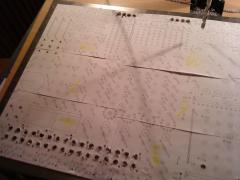
Hi! As I only started blogging, but work on this controller for about a month (plus some planning time), I have to close up to my current status, which I will do today. So the controller is called mothership, because it is rather big :rolleyes: . It will be around a metre to half a metre to fifteen centimetres. It holds controls for four decks inclusive jogwheels, four-section (midi)mixer, an effectsection plus loop-recorder controls. And some other stuff I found very funny, like infrared distance sensors and touchpads. If I can I will try to implement four moto-faders for pitchcontrolling. Additionally I planned a 2x20Lcd to show the selected effect and four Lcd to show some extra info from traktor (traktor has a display-size issue: it will keep its size by "sacrifing" some boxes, so if you use four decks in expanded-mode on a widescreen-display, master volume and other info will not be displayed). The exact layout is done on the frontplate, but I used freeCAD for tests. The idea behind the desing is, despite being desinged for traktor, the overall look of the controller should still be modular, so that it could also be used for other purposes. So for example the upper part of the decks could be used as a step-sequencer (for DAWs), equalizer as pot-matrix and so on. I will use three sorts of buttons: seimitsu-Buttons for exclusive controls, mini-arcade Buttons ( http://www.conrad.de/ce/de/product/701104/DRUCKTASTER-R13-507A-05-SW-TASTE/SHOP_AREA_17384&promotionareaSearchDetail=005 ) and buttons from marquard. Sadly, the mini-arcadebuttons cannot be iluminated, but the have a great feel and are rather cheap for arcadebuttons. Faders and pots are from alps, and I will also implement eight membrane-pots, so I hope that I can supply a calibration-code (in some time). The coloursheme for the leds will be yellow with blue accents. For the electronics I am giong to use three Core17s, with 12DINs and DOUTS and two AINSER64, so I will be busy soldering the next time =). The CORE-PCBs are/will be from SMASHTV, the DIN/DOUT are from MIKEs PCB-Shop (Germany), thanks for the support! I have a USB-hub to connect the cores and for external power (EXSYS EX-1177). I plan to write my own software, but in the meantime I will use the Midio128 one. The controls will be mounted on a aluminium frontplate. I am going to drill it myself, as a custom frontplate would be way to expensive and would not allow me to change the layout along the way. So I will be busy on this part to, I already marked most of the holes, I will use a "Kegelsenker" for the big holes, already tested it it, works good! Most of the buttons can be screwed directly in the aluminiumplate, only the marquard-ones need a PCB, which will be screwn in the plate. The frontplate will sit in an wooden box, I made. For this I doweld four boards on a 1mx0.5m wooden plate. After that sanded the box, doweling more precise means less sandening, I should have paid more attention there... ...so I sanded for hours and hours. I made the corners round and drilled two holes in the back for the USB-hub. The box will be threatened with "Dekorwachs" for a teak-shade. So this is my "current status" and from now on I will give "realtime" updates... Greetings geth PS:Making a mess at home with the midibox electronic stuff...
-
I have a wooden box and a selfmade aluminium frontplate. I have already done a bit more than I wrote, I'm working for about a month on this project, but I only started blogging... =). But I'm trying to fix this today. Greetings geth
-
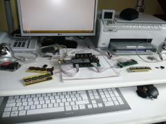
My next step was to build a working core (lpc17) with some DINs and DOUTs. After some troubles ... I succeded. I am really astonished, this device is the least troublesome device I have encountered so far. No extra drivers, just plug and play, and the controller can be unlugged and reconnected while traktor is running, no crash, not even a lag! By the way, the midibox-site is really awesome and must be really a lot of work, so thanks to everyone and especially Thorsten! A pic of my core with a DIN and a DOUT, even got a display for it...
-
Hi, this is my blog about how I am going to build a Traktor-Controller. Well, and if this one turns out good, or at least not too bad, building more controllers. I am playing around with traktor for about two years, and I was never really satisfied with the layout of the (traktor, or other midi-) controllers one could buy. Thus, when I found the ucapps site about half an year ago, I really liked the idea of building a midicontroller myself, but I was not really sure, whether I was capable of such a thing and wanted to invest so much time. But having a electronics and PIC course at university and digging more in the ucapps site did reduce my fear of getting lost in electronics. What really set me of to build one myself was, when I bought the xone dx from allen&heath. I ordered one from thomann. This one had several losened parts inside. Luckily I live in driving-distance to thomann, so I returned this one. I opended the second one, only one losened part inside but a jog-wheel was stuck... . So I took another unit home, which seemed to work, but after several days the usb-connection started to overheat every 30 min so this unit was unusable too. Well, so I decided to do better and to build my own!
-
After long hours of searching the problem systematically, I decided in an act of desperation to resolder every connection on the core and, well now its working. Yeah! On the downside, I do not know where the mistake was (as I checked nearly all relevant connections via dmm I am still clueless). Well, I should have bought an expensive soldering-iron from the beginning... Greetings Geth