

Sim
-
Posts
19 -
Joined
-
Last visited
Content Type
Profiles
Forums
Blogs
Gallery
Everything posted by Sim
-
Hello everyone, I'm not sure if this is the correct place to post this, if not please move it to where it should go. About 4-5 years ago I started on my MB 6582 build. I have all of the parts, completed the top board with the exception of the LEDs, display and the ribbon cable to go between the two boards. I also finished most of the bottom board (forgive me its been a while and I cannot remember the correct names for the two). However at one point during the build, I ran into an issue with one of the capacitors or resistors. I couldn't determine exactly was was wrong, and due to life events I put the project to the side and hadn't really had the chance to work on it sense then. I was wondering if there was anyone in the states that would be willing to check it out for me and possibly finish it up for me due to my lack of knowledge of circuit boards and my concern of messing something else up. This project was much bigger than I had expected, and beyond the scope of something I had the knowledge to tackle. I would be willing to pay whoever could do this (though I would strongly prefer someone who has been around the forums for a while, and is fairly known) as well as paying for shipping. I know this might sound kind of lame to ask for but I really would like to have the finished product, I just don't want to chance messing it up myself. Feel free to ask any questions, and I will answer to the best of my knowledge. I am unable to provide pictures of the boards at the moment, but will add them by tomorrow. Any suggestions are also welcome. Thank you.
-
Thanks Orange_Hand, I found those pictures from you in another post and checked them constantly. I've actually put the board to the side for a few days and plan to go back to it tonight when I get my new soldering tips with a fresh mind. As for the voltages though, I was getting around 11.64v and 5.12v on pins which should be 12v or 5v. I plan to do some resoldering tonight and double check a few of the monolithic capacitors. I'll keep you guys updated. Sim
-
-
-
From the album: MB-6582
-
From the album: MB-6582
-
From the album: MB-6582
-
From the album: MB-6582
-
From the album: MB-6582
-
From the album: MB-6582
-
Got it, sorry about that. Like said I tried to do a close shot of half of each side, then a full shot. Thanks. Sim
-
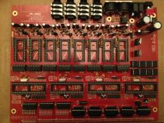
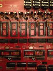
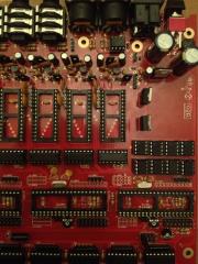
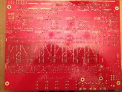
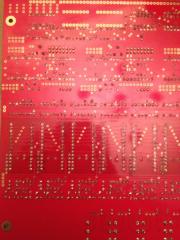
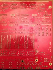
Hey guys, I got some pictures finally. All I have is my iphone, I did my best to get a clear shot. I'll retake if necessary though. Thanks! Sim Top Whole http://i.imgur.com/pCqD3yv.jpg Top half 1 http://i.imgur.com/ekc1Z4M.jpg top half 2 http://i.imgur.com/fXbCmod.jpg Back whole http://i.imgur.com/gImr98d.jpg Back half 1 http://i.imgur.com/Jp4EJBE.jpg Back half 2 http://i.imgur.com/fPvC1VM.jpg
-
Hi everyone, and thank you for the tips. So right now I'm focusing on just the first core/sid pair like Nils suggested (1 core, 2 SIDs, nothing else). Plugged in my SIDs (6581 with the jumpets set to 12v) plugged everything in and turned it on. I had the test tone noise coming through my speakers. I thought it was uploaded with the mbSID software so I uploaded it again, it went through without errors, but still only produced the test tone. So I took out the SIDs (left the PIC in) plugged it back up and tested the voltages. Here's what I'm getting. PIN 28 is putting out 11.64v P25 is putting out 5.11v Then I decided to test some of the other pins. 8, 9 and 15 are each putting put 5.11v as well. Pins 5, 6 and 26 are also putting out some small amounts of voltage. I power down, take out pic, power back up and test. No more smaller amounts of voltage in 5, 6 or 26, but Pin 15 and 9 still put out 5.11v. Sorry I dont have pictures yet, but I will post them ASAP. Thank you again for the help! Sim
-
I'm at work at the moment, but I will get some pictures posted by tomorrow. I actually used 1 6581 to test each SID module (set to 12v of course) which is how I determined the info I posted originally. I had the voltage jumpers set correctly. I tested the voltage of my C64 PSU and I was getting the 5v from the DC pin, however one pin was giving ~10v (AC) and the other seemed to give out ~3v. However the voltage tests on the board all return (pretty close to) the right amount. (12v pins putting out ~11.59v.) I'll do some extended testing of the power supply tonight (I have two others) and check the continuity again. Just a quick question though. My multi meter doesnt have its own 'continuity" setting or a beeper, but I've read online that you can just set it to the lowest ohms setting (mine is 200) and just look for the numbers to change. Do you know if theres truth to that? That could be whats throwing me off. Thanks for the help Peter! Sim
-
Hello everyone, I'm currently working on my own MB-6582 (finally!) I have everything soldered onto the board using a PSU option B build with some 6581/8580 chips. I've checked (and recently double checked) all of the pins for the correct voltage and everything has checked out, however I think I may have a grounding issue in the 3rd SID set, but we can get to that later. Right now my issue simple but confusing. I have done the test tone for SID sets 1-3 (I dont have enough chips for the SID 4 module right now) they won't make a sound with a bit of wire like Wilba's guide mentioned, but they will produce the square wave when I put a SID chip in. After that I load up the MB-6582 software and the issue starts. The first and third SID sets will either produce a similar sound to the test tone, or sometimes nothing at all. The second SID set works, however whenever I try out notes with MIOS studio, it reacts like one key is being held down sometimes really low pitched, sometimes really high pitched. It'll play the note I select, then once i let go it starts the other pitch again. I have the proper jumpers set for 12v, and I have jumpers on J3/J23 on each set to make sure that doesn't interfere. Any ideas would be greatly appreciated! Thanks!
-
Thanks Jojjelito! I would do the bulk order but I'm impatient, haha.
-
Hello everyone, I have a pretty dumb question. I have ordered 15 encoders for my MB-6582 control surface, and the shaft size is 20mm, however I'm not sure what the size of the knobs I order for them should be. I assume they shouldn't be the same (as in 20mm) but I'm not sure. I did a search around the forums to see if this had been asked before, and tried to compare other peoples builds to part sizes but couldn't find any for-sure answer. Thanks for any help!
-
Thanks Hawkeye. I know the general rule is to read all of the documentation before asking questions which I have done, but I felt like some of the information was conflicting. I appreciate your help, and the help of all the others here at the forums. I'm excited to start building once I get my full order ready.
-
Oh, okay so let me make sure I understand. With the MB-6582 you don't need core, DIN/DOUT, or SID modules?
-
So I'm a bit confused. Did you make the case just fit to the MB-6582 boards from SmashTVs shop? Is the CS being held in a similar way to how the sammichSID is setup? I've been gathering information to finally build my own MB-6582 so sorry if these are dumb questions.
-
If anyone is selling their sammichSID or MidiBox SID I would be more then happy to buy it. I live in the US but I'll pay for shipping. Or if you have kits for either one I'd be happy to buy that as well. Just let me know what you have and your asking price!