Highcooley
-
Posts
95 -
Joined
-
Last visited
-
Days Won
3


Highcooley's Achievements
MIDIbox Newbie (1/4)
5
Reputation
-
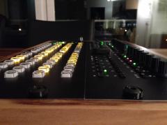
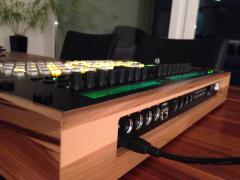
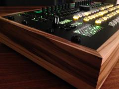
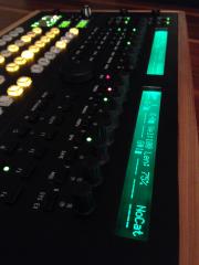
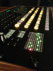
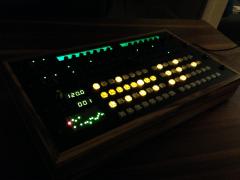
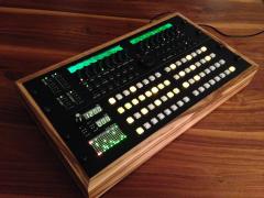
It is finally done, my Midibox NG powered analog synth hardware is finished. Usually, it runs pretty smooth with some occasional hiccups. Unfortunately, the power supply is off by almost half a volt on the +15V rail, so I have to re-tune everything. So, there is still some work to do. The next step will be to finish the software by figuring out a lot of stuff like an individual menu structure, free detuning of my second and third oscillator as well as preset save and recall and sending presets from and to the midibox by sysex. Thank you all very much for your support! I would never have come this far without the help of many passionate synth builders and midiboxers. I'd love to also post some samples. But since our first baby is due in the next couple of days, I can't promise much for the next days, weeks or even months. But stay tuned. I promise, some sound will eventually get posted. Until then, enjoy your hobby and see you soon :-)
- 22 replies
-
- 1
-

-
- midification
- ainser64
- (and 3 more)
-
Just a quick followup: It was indeed a fried pin. After replacing the LPCxPresso board (Rev D) and going through the horror of figuring out how to get the bootloader onto that darn thing (as well as bending all of the header pins on the right side of the board in order to finally ram the displaced row into the headers of the midibox board), my LCD went back to operate perfectly. In case you need to set up a Rev D LPC17 as well one day, better find this post instead of figuring out the steps by yourself:
-

LPC1769 rev D board how to load bootloader
Highcooley replied to gerald.wert's topic in Parts Questions
after a couple of hours going exactly through these steps myself, tripping over exactly the same stumbling blocks and figuring out exactly the same solutions, I find your post ...face palming myself. But at least I can confirm, that it indeed works after a lot of pin bending and ramming the board onto the headers. I also soldered a short wire for the two Ethernet LEDs onto the left side of LED3 and 4. The network connector ones lit up, but only dimly. I guess, I should have done that either onto the right side of the SMD LED's or onto the left side of the corresponding resistors on the LPCxPresso board. But here is how I did it: By the way, that's how the headers had to be bent in order to be able to give them a firm push to fit them onto the headers: ...and I can confirm that the Rev D board actually works with all the midibox bells an whistles (I'm using it with DIO, AIO, SCS, standard 2xmidi IO, USB, Ethernet and a single GLCD). -
Thank you for the compliment as well as your sympathies for the SEQ. Rest assured, the SEQ is all fine and dandy. It is my second project (a full fledged analog synth, based on Midibox NG) I am talking about, which also got a nice looking case. Pictures will follow, as soon as I get the display running. In my case, the two J5s as well as the J4s would be unused, as I'm running a SCS at J10. Also thank you for pointing me into the right direction with the pin mapping file. It is not very appealing to build own explicit hex files of course. Especially, since I am more the hardware guy than the software specialist. But as a last resort, I am definitely looking into that. Concerning the new LPC board, Embedded Artists state, that: If I compare the schematics, the pinout is also exactly the same. There is only an additional RBG LED onboard, which will flash wildly in different colors, since it is driven by three DOs used for other purposes in the midibox standard. So I tossed my money in and ordered a new LPC. We will see, if it works properly and if all goes well, I'll have a spare LPC for a display less midibox application :-) Cheers, Andy
-
Hey everybody As it seems, I fried the R/W output pin of my LPC17 (p1.27 of the LPC1769 xpresso). When I moved my Synth from the cardboard housing over to the new wood case, I accidentally plugged the 5V supply into J27 next to J2, the actual supply pins. The 800mA slow blow fuse blew instantly, so I assumed, that I had shorted 5V to GND of J27 but everything except for the fuse was alright. Of course, the move from one housing to the other lead to a lot of cables being too short and a bit of debugging due to shorts with the front panel and so on and so forth. The last thing to do, was to solder a longer cable to the KS0108 compatible GLCD, which at least for me is always a hassle to get the specific pinout as well as pullups, pulldowns and trimmerpots correct. After the first power on, the LCD started up normally with the init text, but then things got bad very quickly. After a couple of seconds, it continuously started looking more like a snow storm with random pixels being on or off, firstly changing, whenever the LCD was updated, but becoming static after a while. Meanwhile, with each power cycle, I either get a blank LCD or the mentioned snow storm. Of course, I doubted my skills first, checked the wiring several times, also changing RST high and low, but nothing helped. For a short time, I also believed that the 45cm long cable was too long, but the internet taught me otherwise. So I was left with two possible root causes, either the LCD has to be broken or the LPC. With the built in testlcdpin function, I was able to find R/W always being high (not mattering if an LCD is connected or not). This leads to my conclusion, that I probably fried the output of the LPC, since the pin is directly connected to the micro controller on the lpcxpresso board. Is there a possibility to assign another pin as the LCD R/W pin in a config file, so I can cut and rerout it to P1.27 on the lpcxpresso board and still be compatible with future updates? If this is not an option, does anybody know if the newly released LPC1769 board is fully compatible with the old version: http://www.mouser.ch/ProductDetail/Embedded-Artists/EAX00242/?qs=sGAEpiMZZMtWuggIubTlfyQKvxcc1sy3C%2fHLDQO4Us4%3d ? Thanks for your help! I am a bit in a hurry to fix this quickly, since I have to give up my electronics lab as soon as possible to make room for our firstborn :-) :-( :-) Cheers, Andy
-
 I used the following TC011 switches with the 4 button boards I designed a while back, attached in the button's description: The small boards are mounted on four M3 standoffs each with 15mm spacers. In total, it's 16 of these small boards, an additional matrix board for the shift registers and eight ribbon cable strands with 20pin connectors. My initial thought was, that these small boards would be very versatile (which they are) and ultra-cheap in production as a 20 pack of small PCBs is a fraction of the price of one single large PCB. However, this also meant, that I needed 64 standoffs on the back side of the front panel to mount the PCBs as well as many IDC connectors and it also was a lot of work to mount everything. In the end, the additional price for the front panel was about the same as a larger PCB would have been. I also went for single colour buttons, whereas dual colour would have been nicer.
 -
Thanks guys!
-
Finally, my Midibox Seq is done, including a BLM as well as a TPD. Inspired by sineSurfer's wood case, I trained my carpentry skills to accomplish a decent case myself
-
-
Hi Thorsten Ah, I got it. I have to first "save" each snapshot number (like set it up the first time) at least once, in order to "dump" values in it. As it seems, I haven't fully understood the difference between saving and dumping a snapshot. Can you please explain this? What I intend to do is simply store all current set values into a snapshot whenever I hit the button. Can I simply use save every time? How about the multiple banks of presets? Is my assumption correct, that I have to save them in different .NGS which would mean that I need to have copies of all configuration files with the same name as the corresponding .ngs for each .ngs? Thanks for your reply and best regards, Andy
-
Hey everybody Today, I tried to get a step further with my synth and start configuring snapshot functionalities. Unfortunately, I didn't get very far. I can set snapshot numbers and save or dump them. I don't get the exact difference, but I belief that saving means that the last event state is being saved and dump means that all ID's states get saved (except the nodump ones). Can somebody confirm this assumption? As far as I understand, 127 different snapshots (127 times all ID's states) can be saved/dumped into one .NGS file. When I do this (via SCS standard menu or a self configured shortcut using the meta events DumpSnapshot and LoadSnapshot), the NGS file gets a bit larger, whenever I save to a new snapshot number. Also when I load a snapshot, I receive the line "loading snapshot #0 from /DEFAULT.NGS" in the MIOS monitor. If done via SCS menu, I get the confirmation on the LCD saying that all went well. However, no values get set if I load. Or in other words, if I dump two different snapshots and change one toggle button state, loading the snapshots won't load one or the other button state. I do load snapshot 0 in section 0 of my .NGR (at reset). This usually works and I get a "save state" in order for the synth to operate correctly. Unfortunately, sometimes, this dump gets corrupted as well and I have to dial in everything again. (@Thorsten: If you read this, the automatic dump every couple of seconds caused some timing problems which caused short audible interruptions when playing notes, so I had to disable it) Some special configurations of my Midibox could cause problems: - The load Snapshot 0 in section 0 might somehow trigger and reload dump Nr. 0. However, this should not happen and of course I tried without this code line and it didn't change anything. - I do have a couple of LEDs which I set in the .NGR script. I don't know if these get dumped as well and if loading also triggers the events which these sections get executed, so the LEDs get correctly set. - Some rotary switches trigger .NGR scripts which set LEDs in a binary fashion. Again, I am not sure if the states of these LEDs get dumped and if the scripts get triggered after reload. However, it doesn't work with simple events like EVENT_BUTTON id= 1088 type=CC fwd_id=LED:2048 button_mode=Toggle chn= 1 cc= 110 range= 0:127 lcd_pos=1:1:5 label="LFO Freq ^highlow " for example. Unfortunately, I don't get it how the .NGS file is structured in order to check how different snapshots differ. Does anybody have some experience with the whole snapshot thing and can give me some guidance? Should this all work one day, I would like to save some presets. Actually, I would like to try to convert the preset file from the original Moog Voyager and somehow upload these presets onto my midibox. I have Banks from A-E with 127 presets each. As far as I understand, "Bank" and "Patch" cannot be used for this, since these terms are used in different ways as they might suggest. The way I see it, I can do this by saving them in different .NGS files. However, I am not sure, if I have to create .NGC, .NGL and .NGR files with corresponding names in order for this to work as I would like or if multiple .NGS files can be loaded with one set of configuration files. Converting the original presets is going to be challenging, but maybe somebody has an idea how to do this as well? I am running Midibox NG V1.035 by the way. As always, help is very much appreciated. Cheers, Andy default.ngl default.ngr DEFAULT.NGS
-
In case anybody else has a similar problem, here the solution: I figured out that whenever I had mi DSO attached to the FC line, the fourth AOUT_NG module worked fine most of the time. If I detached the probe after the initialisation phase of the midibox, the chip stopped working until I reattached it. This smelled like an AC termination issue, or better to say the lack of it. Since an AINSER64 in series with four AOUT_NG modules results in quite a long total cable length, these problems can occur. Basically, the signals can get reflected at the end of the line causing timing problems between the clock, FC and signal line. My solution was to terminate all three lines with 100ohms and 100pF to ground like the picutre below. Now everything works a treat again.
-
Hi Thorsten Sorry for warming up this thread, but I've got trouble with my fourth AOUT_NG module again. After a break which unfortunately took me a couple of months, I started working on my synth again. I soon noticed, that something is amiss with the fourth board. The outputs don't react at all. To test correctly, I used a config file with a reset command and this single line "AOUT type=AOUT_NG cs=1 num_channels=32". Testing aouts with the caliaout command, I was able to test different outputs from 1-24. Everything worked except 25-32 on last board. Since I am pretty sure that they once did work, I switched the fourth board with a spare one, but nothing. So, I started interchanging boards as well as cables to rule out defective hardware. All boards and cables in any position work except for the fourth board in the chain. I did test with NG V1.033 pre16, V1.033 pre10 and V1.035 Do you have any idea, what could be wrong in the software? Cheers Andy
-
Hi Thorsten Perfect, this command is splendid. Best Regards, Andy
-
Hmmm, nope I was not aware of that. This explains some of the odd behavior I noticed. Is exec_meta SaveSnapshotimplemented? I only get error messages if I have it in an .NGR An .NGR command which only saves if there are changes and also doesn't save more often than every couple of seconds would be very elegant. I won't push a button and switch the synth off immediately afterwards anyways. So only saving if there are changes after 10-15 seconds would be more than enough. Best Regards, Andy
-
Hi Thorsten It hasn't necessarily to be this section. I just want to automatically recall all last toggle button states after each power on. And since I don't see a way, how they could be saved when the power gets switched off, they probably have to be saved every time a button changes its state. I misunderstood the way the LED event works, since I thought it only would get executed once every time it changes its state. But obviously, this happens every time as long as the LED is lit. So this section is probably not the right one to do this dump. But how else can this be done? Best Regards, Andy