johnmx
-
Posts
17 -
Joined
-
Last visited
Content Type
Profiles
Forums
Blogs
Gallery
Everything posted by johnmx
-
-
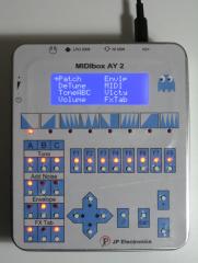
This is my first MIDIbox project.
-
-
-
From the album: johnmx - MIDIbox AY (YM) V2
© JP Electronics
-
Does anyone have patches using the FX Tab for cool sounds (e.g. bass drum, etc.)?
-
Hi lemonhorse, Thanks, but there is no need for that. I got it! The noise is finally working. The chip is not properly self-initialized during power-up as it requires a hard reset (via reset pin). It doesn’t matter what values we write to the internal registers, the noise generator will never work. I use the RD4 port of the PIC for that. I notice that you use this pin to generate a pulse on MIDI events. What is the purpose of that? Only for debugging? Anyway, I commented that part of your code and also the lines 62 and 80 of the file ‘mios_srio.inc’ from the MIOS project. Since I don’t have more AY chips, I would like to ask if you can do this modification and test the Microchip chips. I notice an odd thing. The output volume increases when I change my midi controller to channel 2 and even more to channel 3. After that it doesn’t matter if I change back to channel 1, the volume stays at that maximum. Can you please test if this happens in your box? I'm using the default volume settings. Please note that I didn’t implement the opamp mix board. I have all the three channels short-circuited. Now let me say the major change I did to your hardware design. I could not find a crystal oscillator in my local stores and since they are very expensive, I simply removed it and used the PIC’s PWM as the clock source. For that I use the RC2 port as the 2MHz clock source and RC3 for serial output. The only disadvantage is that the PIC’s crystal it’s not temperature-compensated. For anyone interested here is the code to initialize the PWM peripheral: INIT_USER_PWM ;; JUMPED IN HERE FROM USER_Init ;; Initialize PWM (2 MHz clock for AY) ;; ######################### ;; This avoids using an external 2 MHz oscillator which is very expensive ;; The period is 5xTcy and Duty cycle is 2.5xTcy movlw 0x04 movwf PR2 movlw B'00100000' movwf CCP1CON movlw 0x04 movwf T2CON movlw 0x02 movwf CCPR1L movlw B'00101100' movwf CCP1CON ;; EXIT HERE return
-
 I’m using old sockets >25 years. Old, but new. I mean never used before :)
 -
Hi lemonhorse, I spent all day trying to figure out the problem but with no luck. I found a couple of errors in the code that supposedly were the problem, but it didn’t solve the issue. Both are in the function ‘LABEL_AY_SR_Write’: 1- The bus control signals, BDIR and BC1, must change within 50 ns maximum. Setting both pins using the instruction ‘bsf’ (line 175 & 176) results in 100 ns which is the double of the maximum allowed. Solution: ;bsf AY_SR_LAT_BDIR, AY_SR_PIN_BDIR ;; SET BDIR (AY Chip) ;bsf AY_SR_LAT_BC1, AY_SR_PIN_BC1 ;; SET BC1 (AY Chip) movlw 0x30 iorwf LATC, F The same applies when resetting both control signals at the same time: ;bcf AY_SR_LAT_BDIR, AY_SR_PIN_BDIR ;; CLEAR BDIR (AY Chip Control) ;bcf AY_SR_LAT_BC1, AY_SR_PIN_BC1 ;; CLEAR BC1 (AY Chip Control) movlw 0xCF andwf LATC, F Note: This solution doesn’t use the pin definitions! 2- The minimum time in ‘Inactive State’ between writing the address and the data is not specified in the data sheet. The Timex computer uses a delay of 5.5 us and this program only a 100 ns delay (1 instruction cycle). This may lead to problems. One solution is to add some nop’s or simply set the control signals after updating the 74HC595 latch (don’t forget to keep the control signals stable for at least 500 ns). This last solution is not strictly necessary because the ‘Write Data Pulse Width’ is around 5us and it is inside the limits of 500 ns up to 10 us. According to the data sheets, the Microchip version chip have different timings. I believe this is the reason why your code works with some chips and not with others. As a last resort I ran the following basic program in the Timex: 10 Sound 6,8;7,246;8,15 15 Pause 1 20 Sound 6,8;7,254;8,15 25 Pause 1 30 Go To 10 I can hear the noise being generated. So, the chip is OK. I have measured all the signals (control and data BUS) with an oscilloscope and did a small program to replicate this commands. I put the new routine at the end of the function ‘USER_Init’. It was an infinite loop. I checked again with the scope and the signals were the same in terms of values and timings. But no noise generated…. :sad:
-
Hi lemonhorse, This noise generator bug is very strange because I don’t find any info regarding it on the internet. Well after reinstalling the chip in the Timex, I could confirm that the noise generator is working well. Please remove it from the black list :thumbsup: So, the problem must be in the firmware. I’m going to debug the code.
-
-
-
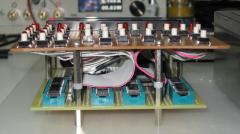
From the album: johnmx - MIDIbox AY (YM) V2
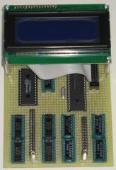
The main board includes the CORE, DIN, DOUT & AY. Here we can see the pin headers to connect the buttons and LEDs.© JP Electronics
-
From the album: johnmx - MIDIbox AY (YM) V2
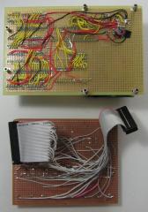
The various modules assembled on a single prototype board. All resistors and capacitors are SMD 0805. Still missing the audio amplifier section.© JP Electronics
-
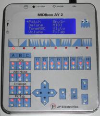
From the album: johnmx - MIDIbox AY (YM) V2
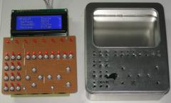
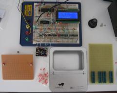
First test to check if everything is working OK.© JP Electronics
-
When I press the “add noise†button, the respective LED lights up but the output sound doesn’t change. So I guess the noise generator of this IC doesn’t work. I’m using the GI’s AY-3-8912A CBA produced on week 44 of 1984. This IC was removed from an old Timex TS2068. You can see the picture I thought that all IC’s from GI didn’t have any problem about the noise generator. I spent more than 20 hours of work to assembly everything on a prototype board and now this f#%#$%# chip doesn’t work like it should :angry: :angry: :angry:
-
Hello lemonhorse, I’m building this prototype. Right now I have a working setup mounted on a breadboard. The link for the firmware version V2.1B (BUILD 20120109) is not working and the latest version available in the repository is the version V2.1 (BUILD 20111128). Can you upload it again? I notice that you have assembled the LEDs F1…F8, but other people don’t. What are their purpose? Should I assemble them? Thanks for sharing this great work.
-
Vivam, Mais um tuga na casa :queen: Conheci o fórum há poucos dias pesquisando no Google. Descobri que o que quero fazer já existe feito e chama-se “MIDIBox AY (YM) V2â€. :smile: Existe alguma página de apresentação para novos membros no fórum?
-
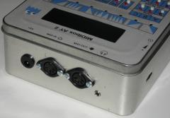
Hi IGI, You made a perfect job with that box, it looks professional. Congratulations! I’m going to build one. Will you be so kind to share some pictures of the inside and back of your box? Also, did you change the program to use all the 20 columns of the LCD? From the picture above I guess not… Thanks! Best regards, Johnmx