urtzurd
-
Posts
23 -
Joined
-
Last visited
-
Days Won
2
Recent Profile Visitors
1,100 profile views


urtzurd's Achievements
MIDIbox Newbie (1/4)
2
Reputation
-
If I were to build the board again I'd probably chose another headers, as the molex ones are too tight. Probably something like: https://www.pololu.com/category/177/0.1-2.54-mm-screw-terminal-blocks Haven't tested them myself, but they might be a better fit. Has anyone successfully used any of those screw terminals blocks?
-
I used these ones: https://m.reichelt.de/Molex-Vielfachsteckverbinder/MOLEX-22012085/3/index.html?ACTION=3&GROUPID=7981&ARTICLE=185655&OFFSET=16&&SID=96WMbx06wQATMAAGj1-PA8d388a3a2ac60bea71117c221d597d2c&LANGUAGE=EN But mind you that the fit is very tight and the ribbon cables are tricky to get properly folded in order to close the case. It's a good idea to use shorter ribbon cables than I did. When I noticed I had already soldered them on the other side and it's quite a PITA to redo them.
-
Thanks for the clarifications! Just wanted to be 100% sure, as I was a bit paranoid with the power issues I had in my previous failed build. Cheers!
-
Hi! Just a quick question on the documentation for the J73 bridge. In this wiki page it says it needs to be soldered for PSU options A and B: http://www.midibox.org/dokuwiki/doku.php?id=wilba_mb_6582_base_pcb_construction_guide On this other page it says that J73 is for option C only (note 3): http://www.midibox.org/dokuwiki/doku.php?id=wilba_mb_6582_parts_list I guess the correct info is the one in the first page, but just wanted to make sure. Thanks!
-
There's some space, but not much. The headers have some space as the control PCB is shorter. It takes a while to have everything aligned when closing it, making sure none of the ribbon cables gets smashed.
-
Thanks a lot for the info! It was a perfect timing for me, as I was trying to get this OLED display working: http://www.ebay.co.uk/itm/131999107925 After soldering the bridges and setting the device ID to use the 8bit driver, it works!
-
I'm updating this post in case someone experiences a similar problem. After some months I got new PCBs and built another MB6582 main board. To my surprise, it seemed that I was having the very same problem as with the previous one. So, I started to do some checks with a cheap DIY oscilloscope and discovered that I was getting some AC power from the ground line. The reason: the replacement power supply I got from Ray had the ground wired to earth, and my place has very dirty earth! I guess that's a common practise in the US, but here in the UK the wiring in some old flats is terrible and you get tons of noise and leaks from your neighbours. I guess that this "moving" ground caused the filter electrolytics after the bridge rectifier to go bad after some time, as they were getting some voltage on the negative lead, ouch! As the replacement power supply was built in a metal enclosure and I needed to have both rails floating, I decided to build my own PSU based on the "dual power supply" that can be found in the forums. I feel safer with a plastic enclosure
-
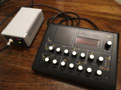
Finally got my MB6582 completed and working. Custom power supply and yellow OLED display.
-
-
MB-6582 board set availability (possible bulk order?)
urtzurd replied to urtzurd's topic in MIDIbox SID
Fantastic news!!!! I just ordered a couple of sets. Thanks a lot Tim for supporting the midibox community!!! -
MB-6582 board set availability (possible bulk order?)
urtzurd replied to urtzurd's topic in MIDIbox SID
Bumping this. I'm afraid that my attempts to contact Tim and TK have not been very successful yet In the meantime let's keep hope that the boards will get back in stock some time in the future. -
MB-6582 board set availability (possible bulk order?)
urtzurd replied to urtzurd's topic in MIDIbox SID
Hi! I tried contacting Tim (SmashTV) some weeks ago regarding this and no response yet. I'm afraid he's not very active in the forum lately. Hope he's well and it's just he's on holidays. Not sure if some of the other Midibox gurus like Wilba or TK could also help us. Let's see if they show around, otherwise will try contacting them too in a few weeks. Fingers crossed, as the MB 6582 is an amazing DIY project! Cheers! -
MB-6582 board set availability (possible bulk order?)
urtzurd replied to urtzurd's topic in MIDIbox SID
Yes, that's right. The idea is to ask TK to make another run of them. I'm assuming that not many of them are ordered from the midibox shop. If there are some of us interested in getting them, that could encourage restocking them. -
Hi there, It seems that the MB-6582 boards have been out of stock for several months. I've been very actively checking the midibox shop with no luck in the last two months. The forum seems to be very slow too, so I'm starting to feel a bit worried. Are there any plans to get another run soon? Perhaps we could run a small bulk order with the users interested in getting some. I'm interested in getting two sets of boards. Anyone else interested, please jump in! Cheers!
-
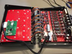
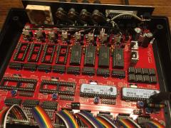
Hi, First of all, I want to thank the Midibox community for such great projects and support! In the last months I've been working building my first MB 6582 and unfortunately I had some strange issues after having it working for some weeks. I'd like to ask for your advise to do a postmortem analysis on what went wrong (more on the postmortem thing later). I decided to go for option B for the power supply, as I want to use both revisions of the SID chips. When I finished the main PCB I tested all the voltages and everything was fine. Then I tested loading the ICs and with the SID chips and it worked successfully. I was very happy and continued working on the control surface, doing some tests with some new SID chips I got from ebay. To power the MB 6582 I was using an old C64 brick. So far everything was fine. Then I decided that I should get some other power supply as these old bricks can die any moment, so I contacted Ray Carlsen and ordered one of his power supplies (great power supplies and great guy). Everything was working OK for a couple of weeks, but after that the new power supply stopped working with the MB 6582: the 9V and 12V rails read very low voltages (around 2-3V). Strangely the old C64 power brick continued working properly. This made me think the problem could be on the new power supply, and after many tests I decided to replace the 9V AC transformer myself, always with the help and advise of Carl. Everything was the same. One day, using the old C64 brick the SIDs were not working and I measured the 9V and 12V rails and they were low voltage too... If I switched the MB 6582 off and on again, most of the times it would work again properly. After that, it was clear that the problem was on the MB 6582, so I started measuring voltages in many places and discovered that the input voltage of the first voltage regulator was around 18V when using the new power supply, and 16V when using the old C64 brick! This was a very bad sign, but it also explained why the one power supply would work and the other won't: the regulator was operating under too much stress and this 2V difference would make it shutdown. Now being on the right track, I decided to replace the electrolytic capacitors and discovered that one had some dark marks on its side. When firing it again I started measuring voltages and thinks looked better, but I accidentally slipped one of the probes and made a shortcut in the voltage regulator pins :-( This blew the fuse in the new power supply, but the 5V part is also protected with a relay, so the power supply survived. Unfortunately I noticed that the other 2200uF electrolytic had dark marks on it. Then I decided to replace all the components on the power circuit, from the bridge rectifier to the capacitors that are after the voltage regulator. Unfortunately my desoldering skills are not very good and when I finished I created a new problem. Now the voltage regulator has a low input around 4V. The bridge rectifier reads close to 9V on its output, but the negative pin relative to common reads -4V. I checked for AC voltage between the outputs of the voltage regulator and it reads around 4.5V AC :-( Then I replaced the bridge rectifier again, and that made quite obvious that I had damaged the PCB contacts, as now I have some exposed copper areas around the pins of the bridge. So it's quite obvious that I have created a short in the PCB (this is why I said postmortem) and I should build a new one once the PCBs are available at the midibox shop. My first diagnosis was that it could be that I placed one of the big electrolytics reversed, but I have a picture of the board when it was working OK and they seem to be in the right position (see attached picture). I'll build a new board from scratch, but I'm still wondering what went wrong and how to avoid it happening again. Any advise or checks would be more than welcome. Thanks a lot and sorry for the long post. Cheers!
-
Hi! I've implemented a very simple circuit to detect if the D-Sub connector is connected. It's basically as you described but using a pull-up resistor, so by default the value of that line is +5V. I use two pins on the D-Sub connector: one connected to GND and the other connected to the detector pin. When the cable is connected, it closes the loop, sending the GND back to the detector pin and switching it to logical 0. This allows me to connect the detector pin with the E line in the display using just one AND gate. When the cable is disconnected, the display is enabled, when connected it's disabled and the external display is enabled instead. Hopefully I'll post pictures soon, as soon as I have some time to work on the case and I get some overlays for the panels. Best regards, Urtzi.