

istel
-
Posts
34 -
Joined
-
Last visited
Content Type
Profiles
Forums
Blogs
Gallery
Posts posted by istel
-
-
Ok, so i just got away from this a little while and came back with fresh eyes. The b11 and b12, b21 and b22 etc are supposed to be connected with jumpers on the male pin headers if i just want unipolar out, right? If i want bipolar i can make the little schematic shown on the AOUT page with a trimmer and some resistors...
I am now going to check out if there is any problems on the core, since i get quite irregular results when i turn on the core - for instance the red LED just lit up on channel 1 and yesterday it did on channel two. Doesn't seem like there is any bad connections on the AOUT board, so i am thinking it is something from the core..
-
OK, i doublechecked the connections between core and aout and it seems it is correct.
When i turned on the core the first time afterwards, the red led on ch 1 lit up for a few seconds, but when i rebooted the core it didn't do it again. Something isn't right with the connections and i am going through my soldering work on the AOUT now.... hmmm!
I also checked all the power supply connections now and they also seem to be good - ie. +/- 12v for the tl074 and 2.048 for the max525 (i measured 2.050, should be ok, yeah?)
-
The gate LEDs are a good indicator, if the Core->MAX525 communication is working or not, because an unconnected bipolar PSU or shunt won't affect this.
Apparently the communication is not working, otherwise the gates would be enabled whenever a note event is played.
Just to doublecheck:
I guess that you are trying this example: http://svnmios.midibox.org/filedetails.php?repname=svn.mios32&path=%2Ftrunk%2Fapps%2Fcontrollers%2Fmidibox_ng_v1%2Fcfg%2Ftests%2Fcvnotes.ngc
Did you change:
AOUT type=AOUT_NG cs=0 num_channels=8
to:
AOUT type=AOUT cs=0 num_channels=8
to select the right protocol?
If yes: doublecheck the connections between AOUT module and MBHP_CORE_LPC17::J19.
Best Regards, Thorsten.
I am actually running the 016_aout tutorial, but maybe i should try out this example you're giving here..
I have connected the J19 like this:
J19:Vs -> AOUT VsJ19:Vd -> AOUT VdJ19:SO -> AOUT SIJ19:SC -> AOUT SCJ19:RC1 -> AOUT CSThat should be correct, right? It is taken from the readme in the 016_aout tutorial.I'll just run through things and doublecheck here and there :)Thank you Torsten -
The Gate LEDs don't light up either, shouldn't they be doing that in the tutorial application? I think i should try and just run through all connections on the aout board. It might also be the 6007b shunt which isn't sitting correctly.
-
Hi
I feel i ask a lot of questions on this forum, but i am very grateful for all the answers
I am currently building the AOUT (orig version) and i just finished the bipolar PSU, plus the board and tried hooking everything up to the my LPC1769 core
The LED lights up on the AOUT and i am running the AOUT tutorial, but i can't figure out if everything is working correctly. I have tried measuring the different outputs on the board with my multimeter but i get a constant reading of around -10v on all outputs, thinking this isn't correct
I am sending loads of different notes and velocity and i can't seem to get it to change values. I had first plugged it in without the bipolar PSU, but figured out that this was actually necessary for the tl074, so i am a little worried these might have taken damage? I think i will try to swap them out and test again and otherwise go somewhere i can measure with an oscilloscope instead.
Any ideas or experiences? I tried searching but couldn't find very much about the AOUT
Thanks again for all the help!
-
...the operating system shouldnt be the reason for your issue. it sounds more like you havent stored the lcd-parameters with the bootloader application. try that first.
also you should try the tiny-font:
MIOS32_LCD_FontInit((u8 *)GLCD_FONT_TINY);
which gives you the maximum amount of letters on your display. if your compiler cant find the tiny-font, update your mios-sources...
mOnO
I am quite sure that i have stored the LCD params. I run the lcd_width, lcd_height, lcd_type, lcd_num_x and lcd_num_y and then store afterwards. It says it is saved. I see how it shouldn't be the operating system, but for some reason it is only when sending applications from his computer that we have the issue.
We'll try out the small font, seems like it would be worth it. Saving every pixel!!
-
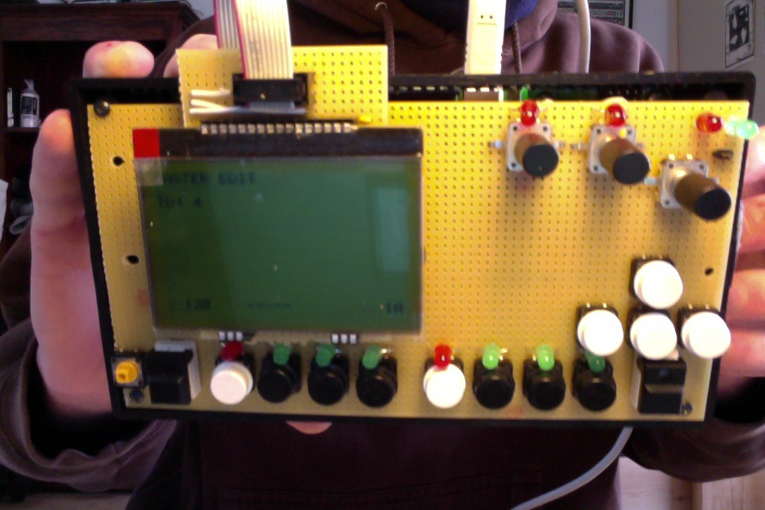
Yeah, this is so nice!! Before it was only a 2x16 CLCD, but this can show so much more info!!
But we are having slight issues - we are two persons working on the software, one OS X and the other is Linux. Every time my friend tries to send an application to the device the screen will fail, and we have to flash the bootloader, update LCD settings and then send the application from my computer (OS X). Is there somewhere where the bootloader config is being set without us knowing? It seems that everytime he tries to send over the application something is being reconfigured with the LCD and it has to be set back to DOG_GLCD, etc etc..
Here is the prototype (!) :)
-
Hehehe! Yes, slightly adventurous! Now it works - i see how it looks a little funny, but i think everything is wired up correctly now.. The error was the caps - i had read the wrong value in the schematic, i thought it say 0.2 uf and not 2 uf :) swapped them out and now it works!
-
Okay, so i tried making it work today. Made a small proto-board to mount the display on and i think i have made the right connection. If i measure on it, there is 3.3 v where there should be.
I have updated the bootloader config to the dog_glcd and set the resolution to 160x104 and it seemed to say it stored it and when booting the core the MIOS terminal says initializing LCD #1, so i think it got it.
I tried running the 021_glcd tutorial and i have updated my ~/.profile and set the lcd to the uc1610. In there as far as i could see the resolution was already set to 160x104, so that should be in order. The code compiles, but when i try to plug in the display and boot the display shows nothing. I haven't got the backlight, but i would imagine that something would still be showing or some sort of sign of life? It should show the "Tutorial #021" (...), but it doesn't.. I am not sure how to debug this.
Here is two pictures (The ribbon cable goes to LPC1769 core J15)

and

-
Did you also consider, that STM32F4 has already 4 MIDI OUT (and 4 MIDI IN) ports in conjunction with the two (upcoming) MBHP_MIDI_IO boards?
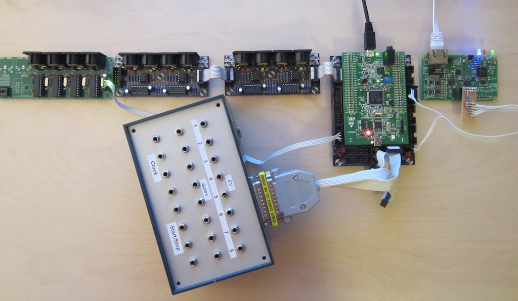
(Ignore the RTP MIDI extension at the right side, and IIC MIDI at the left side...)
This might be the best solution. :smile:
Best Regards, Thorsten.
This sure looks like there is a STM32F4 PCB in the works....... :)
Interesting!!
-
Didn't see all the replys on this topic - i was planning to build this just for the AOUT, but maybe i could switch out the transformer to get more current and tap out 5v DC for the core also? Only having one power supply would be nice :)
I ordered all the stuff, so now i am just going for this, but next time i'll check out the Meanwell.
Thanks!
Isak
-
This is the one I plan on building...
http://www.musicfromouterspace.com/analogsynth_new/WALLWARTSUPPLY/WALLWARTSUPPLY.php
Hmm, i'll just check this out.. Thinking i will make the other one, but i'll see. :)
-
The caps need to be able to withstand the rectified voltage, no need for low esr ones. So use a 25V one: RAD 105 1.000/25 but i would personally take a 2200u one . For the non polarity ones use X7R-5 100N or Z5U-2,5 100N
Thank you Shuriken
Trying to get my head around these electronics one step at a time :)
Isak
-
Hi
I was looking for a straight up BOM for the +/- 12v PSU for the AOUT board, but i can't seem to find any, so i am trying to gather the components for myself based on the center-tap transformer mode http://www.midibox.org/dokuwiki/doku.php?id=bipolar_12v_psu#center_tap_transformer
I was thinking this setup:
7812 and 7912 (pos/neg 12v)
But the caps i am a little confused about - in the guide it says a general rule is 470 uF per 0.1 ampere - the transformer will provide 2x167mA - Meaning something lik 2x470uF on both sides, so around 1000 uF caps - and here i need 1 electrolytic and 1 cheramic for pos and neg side before and after the 7812/7912 - correct? To sum it up:
and then 4 x cheramic/film non-polarity? I can't find any on reichelt with the right specs, they are all in pF which seems like to little (http://www.reichelt.de/Ceramic-Capacitors/2/index.html?&ACTION=2&LA=2&PROFID=256&GROUPID=3159&SHOW=1)..
Hope it makes sense - i am just a little confused with the cap values actually?
Thanks!
:smile:
-
hi istel,
sry, forgot about the RESET. just connect that to Vdd (3,3volts). all the other pins as described before. i wouldnt use a ribbon cable. have placed my dogm-lcd on sockets on the pcb:
this way u can re-use them for other projects. they are really good, but still expensive...
mOnO
okay, sure thing about reset.
yeah, i was thinking of connecting the wires to the back of a proto-board with female pin headers.. i think like you have done, so yeah, you can change
-
hi mono
yeah, i just checked out the datasheet on the dogm.. don't know why i didn't do that before ;)
ok, that looks pretty doable. so i would make a ribbon cable with lines for the SDA, SCK, CD, CS, VDD (3,3v) and RESET? And reset goes to J15/RS?
Thanks for the help! i'll report back if success!! :)
isak
-
Hi
I just received an eadog xl 160-7 (http://www.lcd-module.com/eng/pdf/grafik/dogxl160-7e.pdf) and it seems very nice. Before i just had a normal CLCD on, and i can see that the wiring is different for the DOG.. So i found this schematic, http://www.ucapps.de/mbhp/mbhp_lcd_dogm128_mios32.pdf - but as far as i can see wiring is approximately the same, but there is different terminology on the DOG datasheet and the dogm schematic from ucapps.. Can someone tell me if they are the same? If so, i need to get some 1uF and a 2.2uF caps also apparently, is this also correct?
Thanks!
Isak
-
yes
no, the long leg (anode) has to be connected to the 5V line towards the bottom.
Best Regards, Thorsten.
thanks!
aw, just realized i forgot to order the transistors so can't finish it now :(
anyway, thanks for all the help!
-
ok, next question - i am a little uncertain as to the orientatino of the leds? the green one is with the short leg/minus in right side connecting with max525 gnd leg, right?
and the two red go with short leg/minus towards the bottom?
like this:

yeah? building the aout is a slightly new level for me in having to figure out stuff... ;)
-
Yes, i saw that - but can you see exactly where the three legs of this smaller-than-small chip goes? :)
Yes, you marked the right spot! The side with the single leg goes to the single copper square on your PCB. The two legs on the other side of the 6007 connect to the copper trace and the ground plane. Make sure that you heat up the ground plane with a little bit of solder before you put the 6007 in place. The ground plane will absorb an awful lot of heat, and if your 6007 is already there when you are trying to heat it up it will be fried.Right, nice one! good thing i got a few just in case :)
uhh, this aout module seems like maybe the most exciting thing about the midi box.. being able to send stuff to my modular without going thru midi-cv (and midi's 128 values) and instead 12 bit directly (4096 values, yeah?)
:)
thanks!
-
jep-ah! jeg arbejder på midibox til mit bachelor projekt, dejligt projekt
-
Hi everyone
Got the AOUT board from Mike's midi shop and got the 525 DACs and 6007b shunt, but i am slightly confused as to where to place it. In the guide it says to place it on the back side according to this picture (http://www.ucapps.de/mbhp/mbhp_aout_2.jpg) but it is quite hard to see anything. It's obviously in the middle there somewhere, since it isn't the bridges that i made in the previous step..
Anyway, i took a picture of my board (yeah, some of the soldering is shitty - going to fix that now, haven't tried soldering on a pertinax board before, but it obviously takes a little practice :smile:

Here's the board with where i think it should be placed, but i am little confused with the orientatino..
Here is a picture of the shunt: (so small!!)

So yeah, what i am asking is if it is the correct place and if so, how should the three legs be oriented?
Thank you and thanks for MIDIBOX!!!!!!!! :)
-
Thanks guys - got through to Mike and he could make a few Pertinax for me
I am not sure what to build yet, but right now i am trying to build the software and everything my self - i do alot of midi-cv to a modular synth, but it would be nice to just jump over that step and have direct cv out so that is the plan...
-
Does anyone have the bank info for Mike's shop? I cannot find it and i tried emailing Mike, but with no luck yet.. Just want to get my order on the go asap!! :)
Isak

AOUT problem
in MIDIbox NG
Posted
Sure. This is correct right: