Phatline
-
Posts
1,277 -
Joined
-
Last visited
-
Days Won
71
Content Type
Profiles
Forums
Blogs
Gallery
Everything posted by Phatline
-
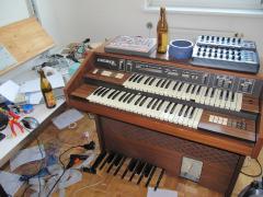 after 2 weeks soldering, finally the first jam sessions with 2 bears and a bit N2O ;)
 -
 the godfathers...
 -
 no internal sound machine anymore
 -
 cut all wires...and connect dark green and orange to get the lower manual working
 -
 bridge the rythm machine to get the lower manual working
 -
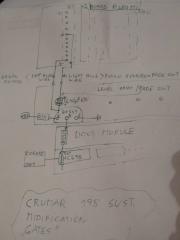
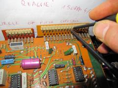 if you want to remove the rythm engine and all it cables... you can cut all cables going to the rythm machine accept....: the dark green and the orange one > you have to connect them togehter in order to get the left most octave of the lower Manual to work...elswere the keys make no sound...
 -
 vectorboard design
 -
 44 keys...88 outpus... read 4 wireing
 -

e-organ, Key-switches to Ground > but Dout Gives +5V how to reverse?
Phatline replied to Phatline's topic in MIDIfication
yes it shares the same ground anyway i realized via BC549 Transistors. DOUT-PIN>10K>Base +15V>1K>Collector Ground>Emitter the whole thing x44 = 500mA... seems the 1K is a bit low ;).... 500mA is not much but.... enough to screw my Powersupply with dry elkos..... -
with midi you dont have to have chains... of course you can make chains....>>>> just build more midi IOs on your MAIN-Box >>> http://ucapps.de/mbhp_midi_io.html....
-
i also would do it via Midi --- or better OSC or Networkcables, to reduce midi cables... but osc on midibox you have to understand first...
-
256 individual inputs, of course but, you can use matrixes and scan that via software, and so you get more that 256 individual inputs.... softwareside i dont have done this... but others have done it... (search for BLM) 256 individual outputs, also can be arranged to matrixes... (also BLM, or SID LED-Matrix, Triggermatrix...), the size of it depends on the Shiftregister (HC595) and its maximal current, but there also alternatives with more current, or transistor circuits to drive bigger matrixes... networkcable - yes - make sure it has pair shields make sure that shields are connected to ground on one side of the cable The DIN and DOUT Modules (digital in, digital out) has to be connected via Connector Socket J1 to the J8/J9 Sockt on the Core Module J1 has 5 Contacts: Put following cables in a pair: VS, VD SI SC, RC To get more Amperes over the cable make it like this: VS VD SI SC,RC I dont know is it clever to put SC and RC in a own shield (pair?): VS, VD SI SC RC tips... well read that: Midibox NG for programming: I did not have to do with the Midibox NG... i took a MIOS32 skeleton and programmed my own concept. and it took a while to understand different things, and many things i dont understand up to now (like OSC and Ethernet) best you use Midibox NG... they have thougt about how a Midicontroller should work. when you want to use your concept of only core, and want to add more modules after time or on a running system, you have to add an "OFFSET to your shiftregister pin-outs) ....for example: activate a LED on a new connected module: LEDs are connected to Shiftregisters mainly "HC595" this registers have 8 PINs, you want to activate LED0 now, LED0 is connected to Shiftregister pin 0, All Shiftregisters are in an chain >>> all registers are connected serial one after a nother...if you connect your EXTRA/Modular Midibox to your CORE/MAIN-Midibox - then the chain starts on the core modules, and goes thru all DOUT-Registers in the MAIN-Midibox, until it goes to a connector where you plug your EXTRA-Midibox... well lets say there are 4 Shiftregister in the Main Midibox, the EXTRA-Midibox now starts with the 5th Shiftregisters... a LED gets software side activated in a way like this (pin, pin_value), so the first pin of your EXTRA-Midibox is: 32 (the pins start by 0, and 4 Registers * 8 Pins = 32 32+0 =32) so the point is, you have to program a offset to this >>> pin+Offset=real pin >>> the offset could be set by a "Connector switch", a Switch which is Connected to a DIN-PIN, if this DIN-Pin is acticated the Software set a PIN-Offset .... like an DEVICE ID that are my thougts... a LED on a specific pin (maybe pin 0) on a shiftregister (a shiftregister has 8 pin
-
e-organ, Key-switches to Ground > but Dout Gives +5V how to reverse?
Phatline replied to Phatline's topic in MIDIfication
checked the datasheet... i tryed 1K Resistors to 15V on the output but with that i got in "low Mode" 1,5V.... high 15V.... but i need 0V @low? a little bit info pleas- thankz -
no i would go for twisted pair - shieldet in pairs, or better individually. daisy chain... yes possible and necessery! all the used shiftregisters has to be connected one after a nother --- and if change the connecting you have to change your Coder!!!! (pin) it depends on your code - (memory on ic) and on the hardware: 256 buttons or 128encoders.... the same for DOUts but 16Led rings needs 24 dout pins http://www.ucapps.de/mbhp/mbhp_dout_8x16leds.pdf i dont made ledrings up to now...so someone other can help!
-
With one Brain hmm i see: 1. connect the boxes via 5pole shieldet cables (used for Shiftregister and Current) > CAT-Cable, and really keep them short! or 2. Use LINE-Driver - Boards to expand the cable length http://ucapps.de/mbhp_line_driver.html
-
e-organ, Key-switches to Ground > but Dout Gives +5V how to reverse?
Phatline replied to Phatline's topic in MIDIfication
a uln2803 for S-Trig... yes that makes the job any idea for a transistor array for a V-Trig 15V? for my other organ? @the moment i use BC337...by the way the Caps make the Piano-Trggers, while the standart output of the BC337 make the Hold-Organ-Trigger -
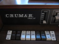
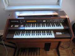
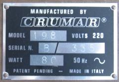
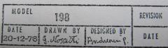
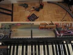
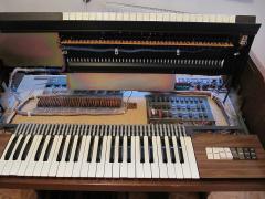
Midificate the ORGAN CRUMAR 198 add my Software "Triggermatrix" > to have some Playhelp with beats...
-
-
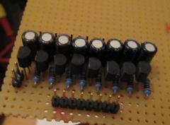
From the album: CRUMAR 198 Midification
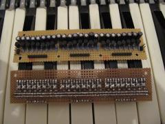
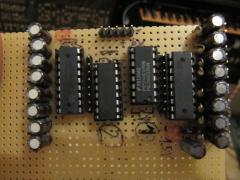
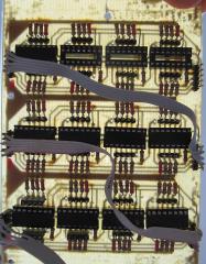
this is not a part for the Crumar organ... the crumar gates are V-Trigger @ 15V but i have a other organ that needs S-Triggers --- for that i made this board - 16 notes, 2xhc595 and 2x uln2803A -
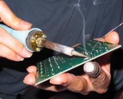
From the album: CRUMAR 198 Midification
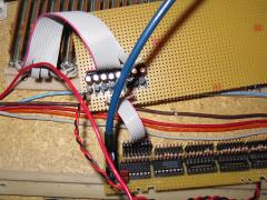
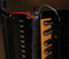
rewireing the gate circuit -
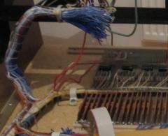
From the album: CRUMAR 198 Midification
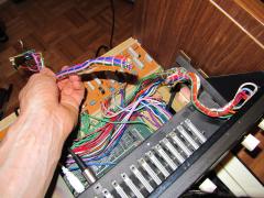
again 90 cables -
From the album: CRUMAR 198 Midification
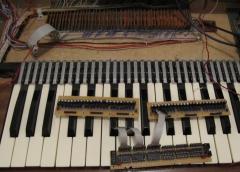
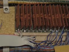
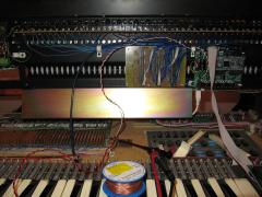
cut the gate cables, but only remove the piano-gate cables from the manual pcb.... we need the organ cables to wire it to the din module ---the organ cables are the Deep-Blue-Coloured-Cables -
From the album: CRUMAR 198 Midification
Orginal wirering of the upper manual about 90 cables! -
From the album: CRUMAR 198 Midification
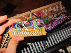
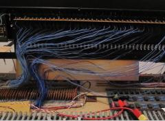
the manual is wired to the DIN-Module -
From the album: CRUMAR 198 Midification
a self etched DIN-Module on a Euro PCB -
From the album: CRUMAR 198 Midification
to reuse the manual itself, i have to change the contact iron from +15V to ground....ground is what a DIN Module needs