-
Posts
1,277 -
Joined
-
Last visited
-
Days Won
71
Content Type
Profiles
Forums
Blogs
Gallery
Posts posted by Phatline
-
-
try:
upload the newest bootloader (with mios studio + http://www.ucapps.de/mios32/mios32_bootloader_v1_018.zip), reboot, on mios-studio - go to the mios-terminal-section, and type "help", then change to LCD type, the number off characters (2x40) and the numbers off X and Y Screens you have on your sequencer... then type "store" (was it store...save...? no idea, all commands are listed when you type "help") the core reboots and you will see some Text on your screens - then you have prooved that this is no hardware issue, then upload the newest LPC17 Seq V4 firmware, then report if it is still Black Blocks you see.
by the way is your "orginal old core setup"?
has the LPC-core ever worked? if not, try to replace the HC595 chip on it (IC2), also check the solderpoints that have to do with the LCD-Section (see the shematic: http://www.ucapps.de/mbhp/mbhp_core_lpc17.pdf) ... Specially the groundpins, since we have a ground plane here, the plane sucks away the heat coming from the soldering iron, give enough heat on your solderstation, and heat the pins longer then normal... but bevore remove the lpc board, and IC2, so you dont destroy them...
thats all - what comes in my mind. -
ok - i wrote sauren.
if i get feedback from him - that he have a pcb - then i ask you @Smithy again - if you still have a pcb-frontpanel then.
- mike.
-
On 1/15/2024 at 9:53 PM, Smithy said:
Update especially for people who have ordered Sauraen's Front Panel PCBs.
TLDR: I have 4 Front Panels and 4 Rear Panels for MIDIbox Quad Genesis for sale.
Life got in the way of both me and @ssp, and we lost contact for a few years!
Thanks for your help dude, and if anyone would like acrylic panels laser cut you should contact him!
The good news is that I ended up converting the Front Panels in .fpd format to PCB format using Kicad with lots of editing and learning.
Here's how the Front Panels came out:hei, what do you payed on jlpcb for one set (devidet)?
is there a change to get a Sauren Frontpanel PCB anywhere?
- i am interested - but not sure that i get all i need to build this (the FM-PCBs are sold out - as example: https://midiboxshop.bigcartel.com/product/midibox-quad-genesis-board) -
maybe its the Ripple off the PSU
about your PSU - reichelt specs is saying : "Ondulation résiduelle : 80 mVcàc" i guess this is not a 50Hz ripple but HF ripple...
--- i guess some small cap (100nf, 10pF) and a big Cap (depends on the load, use for example a 100uF and a 2200uF) on the output off the PSU would reduce that "ripple"...
* maybe that caps are not enough and you need some more filtering (coil, resistor, lpf...) but i would start with some caps...
the connections in your 2nd picture are not necessery - i guess (dont seeing the whole picture, but i think so...) --- so picture 1 is correct.
by the way - its only the last LED that flickers? maybe you have to terminate the DO line on the very last LED off the Chain with a 10K resistor to 5V or Ground.
else it could be a software problem, when the software loops thru the LEDs, and when it comes to the last one it jumps to the beginning off the chain... try to programm in the ng code one more LED (which in reality not exists) - so you can be sure that this is not a software bug...
- but dont ask me about ng-programming --- no glue about that.
- mike.
-
 1
1
-
-
I sale them:
2x with wite SMD LEDS: (for Acrylic Panels without Thruhole) - these are the only two boards with ENCODERS with inbuilt pushbuttons30€ the PairSOLD to KSIR!2x with RED 3mm LEDs - mounted flat to the pcb (for Acrylic Panels without Thruhole)
30€ the Pair
1x with Yellow 3mm LEDs - mounted flat to the pcb (for Acrylic Panels without Thruhole)
10€
2x with RED 3mm LEDs for thruhole Mounting
20€ the pair
I dont have Encoder-Nuts for them.
Shipping only to the EU
why i sell them? > i dont need them... if i am in need i would design my own pcb...
-
new price 800€
-serviced yesterday.
-
two songs in this video sequenced with Triggermatrix 5 as drum-step-sequencer and note processor, feeded with melodys coming from the LoopA
-
-
made a few changes on the cooling:
Made 3 holes where the ventilator "should be"
Drilled the 2 M3 Mounting holes on the right to a bigger diameter
Drilled a hole near the 7809
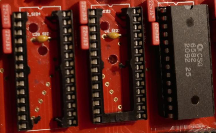
cuted also the second "bar" off the IC-Socket (left socket) - before i had only cuted the top one (see middle socket)i had fear that it would not hold in the socket, or they would bend to much... but the SID hold the socket togehter once it sits in it.
so i have even more thermal pathes...
lets see what this changes on temperatures:
SID: 48-55C°
PIC:36-37C°
Bottom Case: 32-38 (on one point 45C°)
7809: 45
pcb near 7809: 32-37C°
Frontpanel: 32C°
Backpanel: 32C° -
well then test like i suggested:
Voltmeter black cable to a ground pin (core ore dinx4 module)Voltmeter red cable to a Dinx4 Pin that is connect to a PAD.
if you dont press the PAD you should have 5V (its pulled high with the Dinx4 inbuilt pull high resistor > the 10K ones)
if you then press the PAD you should have 0V (its pulled down with the button that connects now the Dinx4 Pin with Ground)
if this is not 0V, and in worst case 2.5V - then the Resistance between Button and Ground is to high, so the 10K resistors which are connected to +5V overrule them... the Chips on the Dinx4 recognize 5V to 2,5V as high (cant say if this is true i think its arround 2,5V) and 0-2,5V is low
my suggestion is now, take one off the 10K resistor out and replace it with a 100K resistors, measure again, and see the difference.
about NG: maybe ZAM knows more... i am definitvly the wrong one for NG script ;) -
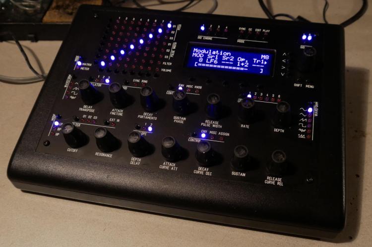
Now a Purple Passive Cooled is alive:
Temperatures after 1,5h:
Front panel: 29-31C°
Bottom off the Box: 30-43C°
Back panel: 28-40C° (40C° on the Plastic above the Ventilator-Air-Hole, 33C° above the small Air holes)SID-Chips: 45-54C°
7809: 44C°
PCB near 7809: 40°C
PICs: 36°C
I will drill some more holes, and post some measurements later on.
this picture is near off the Color that it in reality has... but the camera cant face this UV things good:here where the case color is like it looks in reality (but not the LEDs)
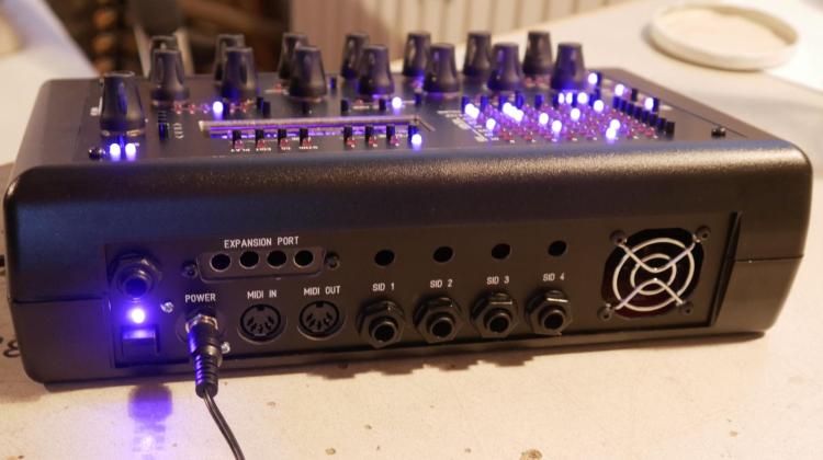
back plate, with some AIR Holes, since it is a passive Cooled Design:
I made a single PSU option (+12VDC) that on the 5V Rail i used a Traco Power Switching Regulator (which is cool)
on the 9V Rail i used a standard 7809, which i mounted on a ALU-Cooler, which i mounted with thermal paste everywhere around on the PCB, the screw thru the PCB i fastened again with thermal paste everywhere, on the blank Ground-Plane off the PCB,
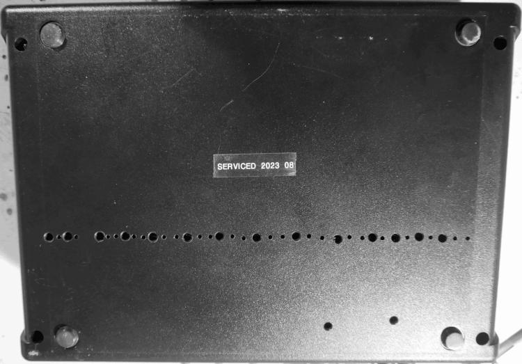
On the bottom off the Case i made a lot off Holes so Air can get in...(the 2 holes under the SID is a Air Intake, and i also cut away the plastic off the DIP-Socket so Hot Air behind the SID can get away.... there are also holes on the bottom off the Case for some Air intake!)
(i drilled away some plastic from the MIDI-Sockets, and also from the PCB , so i can safely mount a Power-plug into the back panel, the Takeaway from the PCB is also some way to get rid off some hot air, coming from the underside off the PCB where the 7809 produces heat)
In this picture you see that i soldered a 220nF Cap between the Reset Line and Ground off the SID... this took a way a high chirping sound out off the equal loud noise floor... I tried different other things to reduce noise, switching a 9V Switching Regulator to a standard 7809 made nothing hear able difference, also by adding LC Filters on the 5V Rail changed anything... this 220nF made the most difference in sound quality (and off course the EXT-IN>Ground Jumper :)
(the screw is the Thermalthienk for the 7809)
single wires to the Frontpanel is for me the best solution:
i also used on the whole PCBs Pb Solder, the melt with slower temperature, and is more fluid, this is good for this PCB because the VIA Spacing between Solder point and Groundplane is almost not existent, so Shorts cant happen so easy... -
since you dont use a Button Led Matrix on this - where the driver is already programmed to be debounced... and you on the other hand connect the buttons directly to a DIN-Module - which i didnt have done yet, on the hardware side i would take a Voltmeter, and measure on the DIN-Pins, hand look how many Volts you have when you press the button... if it is 0V then all is good, if it is hardly above that, then you may change the Pull-Hi Resistors on the DIN Board to a other (higher) Value (As expiriment) - because the Rubber button is not a perfect Electric Contact (a tactil switch is more on "perfect) it might be that it cant Pull-Lo the Pull-Hi resistors (fighting)
@ software
you have to debounce the buttons in software - how?
i dont know the NG-script - so i cant help much here... maybe you start by posting how you defined the buttons in ng code... maybe i can see there something... It could be that there are set as toggle switches, in reality we wont some momentary switch - ... maybe there is also some timining offset to be set (a time that says that no incoming DIN signal is handeld after a trigger accoured - so we avoid false triggering for example 20ms long... aka debouncing?)
-
all encs are working? so its confirmed they start count with nr 1? thx 4 info.
-
are you sure that Encoders start with Number 1?
At least on Midibox-platform on the codeside (if you write a custom Midiboxproject) normally they start with Number 0, (also Buttons, AIN, Midichannels, CCs, Notes, i guess also Ledrings? ;) ;) ...)
that would look there like this:const mios32_enc_config_t encoders[3] = {//(SR count-begin with 1, ENC with 0) // setup the Pinout of Encoders { .cfg.type=DETENTED1, .cfg.speed=SLOW, .cfg.speed_par=1, .cfg.sr=8, .cfg.pos=0 }, // 0 PAGE { .cfg.type=DETENTED1, .cfg.speed=SLOW, .cfg.speed_par=3, .cfg.sr=8, .cfg.pos=2 }, // 1 PAR 1 { .cfg.type=DETENTED1, .cfg.speed=SLOW, .cfg.speed_par=3, .cfg.sr=8, .cfg.pos=4 }}; // 2 PAR 2 u8 i; for(i=0; i<3; ++i) { MIOS32_ENC_ConfigSet(i, encoders); }
they start with 0....
no idea if Thorsten, made it more "musican friendly" by make an offset "+1" behind the userinterface - so they start with 1 on Midibox NG?my nose says....
give it a try:
ENC n=  1   sr= 1  pins=1:0   type=non_detented
ENC n=  0   sr= 1  pins=3:2   type=non_detented
ENC n=  3   sr= 1  pins=5:4   type=non_detented
ENC n=  2   sr= 1  pins=7:6   type=non_detented
ENC n=  5   sr= 2  pins=1:0   type=non_detented
ENC n=  4   sr= 2  pins=3:2   type=non_detented
ENC n=  7   sr= 2  pins=5:4   type=non_detented
ENC n=  6   sr= 2  pins=7:6   type=non_detented
ENC n=  9   sr= 3  pins=1:0   type=non_detented
ENC n=  8   sr= 3  pins=3:2   type=non_detented
ENC n=  11   sr= 3  pins=5:4   type=non_detented
ENC n=  10   sr= 3  pins=7:6   type=non_detented
ENC n=  13   sr= 4  pins=1:0   type=non_detented
ENC n=  12   sr= 4  pins=3:2   type=non_detented
ENC n=  15   sr= 4  pins=5:4   type=non_detented
ENC n=  14   sr= 4  pins=7:6   type=non_detented
-
EDIT: First try my second post (see below this one)
try to not assign Encoder 16, and watch which 2 Buttons now are see-able in mios studio when turning the ENC 16 --- is it 29 30?
since ENC15 is outputet as Buttons 31 32 in Mios Studio - so we can check if it is a neightbar on SR4...
How ever - i guess you use a encoder pcb which you use 2 times in your setup, so ENC 7 is the same as ENC 15? and ENC7 is working as it should? try to to not assign ENC 7+8 - it should be the same pinout like ENC15+16 (but a other Shiftregister)
some math: when ENC 15 is equivalent to Button 31 + 32, then ENC 7 movements should be button events = 32-16 = button 15/16, and ENC8 would be? 13/14? if so > 14+16 = 30 31 should be then Encoder 16?
i checked your shematics, and there is no change to wrongly assamble the sandwitch (the button pins are always on the outside of the Header J30-J33 - so this cant be the bug...i guess u use standard DINx4 Modules to connect the boards, so a wrong pinout from this side cant be the bug too...
at NG Code i am familar with assigning Encoders to shiftregisters and pins > and it seems ok to me (when it is correct that Encoders starting at ENC Nr1 and not at ENC Nr0?)... about the rest of NG i have no glue.
-
j2/j17 should do the trick yes.
-
 1
1
-
-
with midi monitor you mean the mios-studio? http://www.ucapps.de/mios_studio.html
there you will see only the usb-ports (4 off them normally)
the DIN-Boards you have on your sequencer are for IIC and UART and are adressed from your Sequencer - not from the USB-Ports (at least i can remember)... there might be some midithru in the firmware to adress the UARTs via USB- might be might be not, since i dont own a sequencer - i cant say...
isnt there a hardware configuration file that you have to put on your sd-card (which you then put into the sequencer) - normally there you will activate Midiports? you can look into that... maybe Din Port 32 33 34 35 are not activiated? you may post here the text which is in this config file.
a lot off guess i know... -
the ssd1306 oleds i received where 5V tolerant... the ws2812b is also in a range from 3.3-5.3V, dout modules also needs 5V... so your reichelt psu should do the job, and you could power them directly from the psu... but i guess you power them with the ribbon cables from your core...
i dont know what Core you will use? if you use the WCORE from midiphy, then you may ran into some problems when using a external 5V PSU, see this topic:https://forum.midiphy.com/d/151-wcore-non-usb-powerd-but-still-use-as-usb-device/5
also if you are unlucky you will get walking lines on your SSD1306 screens... then it best it would to buffer each D0 D1 Clock... Pins, which are done for example in this module:
http://wiki.midibox.org/doku.php?id=displaydriver-smda plus is then you can then use more then 8 screens!
-
 1
1
-
-
Hei
I have some SPI problems here... A AINSER slows down the SD-Card Access - so the programm is not usable anymore.
I already optimized the Ainser-Side (see below), but that is not enough, I dont know if it is the prescaler Factor, that also changes SD-Card in a way (since booth are SPI...)
I save a lot off informations on the SD-Card, so each percent off performance makes seconds off less waiting time.
Is there something like a prescaler that can be set for the SD-Card?=
How give the SD-Card more priority? I know how to give prioritys for RTOS Task that i created, but i dont know how to do that with SD-Card (on rootlevel)
thx for any info!
I have 2 AINSER8 moduels connected to a STM32F4(disconver), not multiplexed - i have 16 faders connected directly to them.
as soon i scan the AINSER:static void TASK_AINSER_Scan(void *pvParameters){ // This task scans AINSER pins and checks for updates portTickType xLastExecutionTime; xLastExecutionTime = xTaskGetTickCount(); while( 1 ) { vTaskDelayUntil(&xLastExecutionTime, 10 / portTICK_RATE_MS); // 202 orginally 1ms // scan pins AINSER_Handler(APP_AINSER_NotifyChange); } }
The Write or Read on the SD-Card goes up from 1seconds to 14seconds (in my case)
so i copied the ainser.c to my project, and made some edits, the most significant emprovement was to change the prescaler from 64 to 8:
// init SPI port for fast frequency access
MIOS32_SPI_TransferModeInit(2, MIOS32_SPI_MODE_CLK0_PHASE0, MIOS32_SPI_PRESCALER_8); // Initialisierung des SPI-Ports
i also tryd other values, but on some values the Ainser didnt react at all, or i got random values.
When i remove this Prescaler LINE, the AINSER gives no output to my code, what makes me a bit wondering since in MIOS-FUNCTIONS there is statet:
QuoteJ19 provides two RCLK (alias Chip Select) lines.
It's a software emulated SPI, therefore the selected spi_prescaler has no effect! Bytes are transfered so fast as possible. The usage of MIOS32_SPI_PIN_DRIVER_STRONG is strongly recommented ;)
DMA transfers are not supported by the emulation, so that MIOS32_SPI_TransferBlock() will consume CPU time (but the callback handling does work).So my expirience - the Prescale may not have a effect on SPI2, but on SPI0 (where my SD-Card is connected).
I also changed to get this Prescaler8 working, The driver from MIOS32_SPI_PIN_DRIVER_STRONG to MIOS32_SPI_PIN_DRIVER_WEAK (which is i know not recommented):
// pins in push-poll mode (3.3V output voltage)
MIOS32_SPI_IO_Init(2, MIOS32_SPI_PIN_DRIVER_WEAK);	// 2: Ainser_SPI - J19
i then tryed to remove the Multiplexer Code, and fixed the modules to a count off 2,
At the end i have 4 seconds Access Time to my SD Cardwhich was without AINSerial 1second
And without my modifications 14 seconds
I already set the priority off Tasks like this:
// TASK   - PRIORITYS
#define PRIORITY_TASK_SEQ	( tskIDLE_PRIORITY + 5 ) // higher priority than MIDI receive task!
#define PRIORITY_SD			( tskIDLE_PRIORITY + 3 )
#define PRIORITY_LOPRIO		( tskIDLE_PRIORITY + 2 )
#define PRIORITY_LCD		( tskIDLE_PRIORITY + 0 ) // idle
#define PRIORITY_PAD		( tskIDLE_PRIORITY + 0 ) // idle
#define PRIORITY_TASK_AINSER_SCAN ( tskIDLE_PRIORITY + 0 )	// orginal this was 3
So the SD-Task (where i write things on the SD-Card with mutexes and stuff...) is already High priority > off course the SEQuencer is higher...
the whole Ainser.c code then looked like this:#include <mios32.h> #include "ainser.h" #include <string.h> ///////////////////////////////////////////////////////////////////////////// // Local variables ///////////////////////////////////////////////////////////////////////////// static u8 ainser_enable_mask; static u8 ainser_muxed_mask; static u16 ain_pin_values[16]; //2 Modules 8 pins static u16 previous_ain_pin_value; const u8 pin_lookup[8] = {7,6,5,4,3,2,1,0}; ///////////////////////////////////////////////////////////////////////////// // Local Prototypes ///////////////////////////////////////////////////////////////////////////// static s32 AINSER_SetCs(u8 module, u8 value); ///////////////////////////////////////////////////////////////////////////// //! Initializes AINSER driver //! Should be called from Init() during startup ///////////////////////////////////////////////////////////////////////////// s32 AINSER_Init(u32 mode){ // pins in push-poll mode (3.3V output voltage) MIOS32_SPI_IO_Init(2, MIOS32_SPI_PIN_DRIVER_WEAK); // 2: Ainser_SPI - J19 // orginal this was MIOS32_SPI_PIN_DRIVER_STRONG MIOS32_SPI_PIN_DRIVER_WEAK // ensure that CS is deactivated AINSER_SetCs(0, 1); // CS für Module 0 AINSER_SetCs(1, 1); // CS für Module 1 // Dont use Muxes ainser_muxed_mask &= ~3; // Sets the enable mask for modules which should be scanned ainser_enable_mask |= 3; // clear all values memset(ain_pin_values, 0, sizeof(ain_pin_values)); previous_ain_pin_value = 0; return 0; } ///////////////////////////////////////////////////////////////////////////// //! This function should be periodically called to scan AIN pin changes. //! A scan of a single multiplexer selection takes ca. 50 uS on a LPC1769 with MIOS32_SPI_PRESCALER_8 ///////////////////////////////////////////////////////////////////////////// s32 AINSER_Handler(void (*_callback)(u32 module, u32 pin, u32 value)) { static u8 first_scan_done = 0; // Variable zur Verfolgung des ersten Scans // init SPI port for fast frequency access MIOS32_SPI_TransferModeInit(2, MIOS32_SPI_MODE_CLK0_PHASE0, MIOS32_SPI_PRESCALER_8); // Initialisierung des SPI-Ports // loop over connected modules int module; int chn; for (module=0; module<2; ++module){ // Schleife über die angeschlossenen Module for (chn = 0; chn < 8; ++chn) { // Schleife über die Kanäle AINSER_SetCs(module, 0); // Setzen des Chip-Select-Pins auf LOW MIOS32_SPI_TransferByte(2, 0x06 | (chn >> 2)); u8 b1 = MIOS32_SPI_TransferByte(2, chn << 6); // Übertragung der Datenbytes über SPI u8 b2 = MIOS32_SPI_TransferByte(2, 0); AINSER_SetCs(module, 1); // Setzen des Chip-Select-Pins auf HIGH u8 pin = pin_lookup[chn]; // Berechnung des Pin-Index u16 value = (b2 | (b1 << 8)) & 0xFFF; // Kombination der Datenbytes zu einem Wert previous_ain_pin_value = ain_pin_values[module * 8 + pin]; // Speichern des vorherigen Pin-Werts int diff = value - previous_ain_pin_value; // Berechnung der Differenz zum vorherigen Wert int abs_diff = (diff > 0) ? diff : -diff; // Berechnung des absoluten Werts der Differenz // Überprüfung, ob der Pin-Wert sich ausreichend geändert hat if (!first_scan_done || abs_diff > 31) { ain_pin_values[module * 8 + pin] = value; // Speichern des neuen Pin-Werts if (first_scan_done && _callback && pin < 8) _callback(module, pin, value); // Aufruf der Callback-Funktion } } } if (first_scan_done == 0) first_scan_done = 1; // Setzen der Flag, dass der erste Scan abgeschlossen ist return 0; } ///////////////////////////////////////////////////////////////////////////// // Internal function to set CS line depending on module ///////////////////////////////////////////////////////////////////////////// static s32 AINSER_SetCs(u8 module, u8 value){ switch( module ){ case 0: return MIOS32_SPI_RC_PinSet(2, 0, value); // spi, rc_pin, pin_value // 2: SPI - J19 case 1: return MIOS32_SPI_RC_PinSet(2, 1, value); // spi, rc_pin, pin_value // 2: SPI - J19 } return -1; }
i use to write to SD-card directly with File.c, like this:
// Speicherung der Daten auf der SD-Karte
MUTEX_SDCARD_TAKE;
FILE_WriteOpen ("0.p4", 8);
FILE_WriteBuffer(buffer2, sizeof(buffer2));
FILE_WriteClose();
MUTEX_SDCARD_GIVE; -
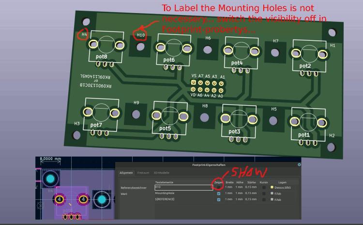
@ Faderboard 1 & 2
Mounting holes labeling not necessery again.
rest is ok.
you may could label + and - beside the 2x5 shroudet Pinheaders, so there is no chance someone reverse it in a way... in generell... normally the Nose- says all, but someone could crimp the cable incorrect... so if he controll measure, this is a good hint then for him.
-
 1
1
-
-
@ pusbutton:
the LEDs in the shematic are REVERSED
for example look into: http://ucapps.de/mbhp/mbhp_doutx4_32leds.pdf
but in the board itself the Silkscreen for the Diode is painted correct - so if somebody just solder the PCB without looking into the Shematic - all is good, when someone look into the shematic he may be confused a bit.
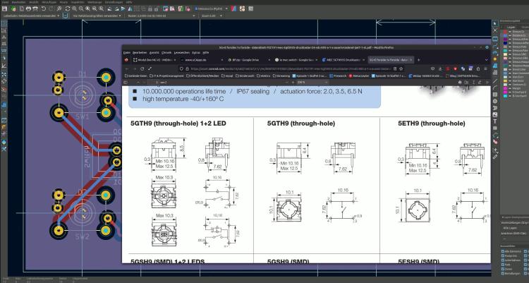
what type off Switch are using here > type it on the silkscreen - like you did on the Potentiometerboard.
because: i see in the footprint its a le mec > then there are different types, with different Switch contacts - like you see here:
5GTH9 + 5ETH9 will work, while 5GTH9 with inbuilt LED will not work off course...
i for me find the correct switch matching to your PCBs Footprint-Pinout - a bit hard... so label the type....
the rest off the PCB looks ok.
-
 1
1
-
-
-
which do you think are completely finished?
at Inverting - something like this:
www.siglgut.at/temp/encoder-phatty.zip
@ ULN2803... normally used to drive Ledrings - because off Currentlimitations off HC595ers... didnt see them on DINs normally?!
@ lack off space > use 4 Layer PCBs.... dont use Thruholeparts like your 10K Resistor network - since it will steal space on all layers - better use SMD single resistors there (when you think in Multilayer), when handsolder then you can place them on top or back where you want... if pick and place then off course only on one side...
Those 2x5 Pinheaders are also aviable as SMD Parts (and also on JLCPCB as Pick and Place Parts) ... Those Pinheaders in Action on a 4 Layerboard:
thinking in this terms - there is plenty off space, and you could arrange then with this new space the Shiftregisters and its Datalines in a parallel manner (at least it will be easier)
-
maybe by removing the pull-Hi resistor off the HC165 Circuit, and using a Inverter on its inputs
for example:
https://www.mouser.at/ProductDetail/Nexperia/74HCT1G14GW-Q100H?qs=SKY61BOKKY4Uv%2FaFLc8SsQ%3D%3D
https://www.mouser.at/datasheet/2/916/74HC_HCT1G14_Q100-2937184.pdf
(just a example maybe there are better parts for this porpuse, and i dont know how hard to solder this one is)
that would reverse Lo and Hi, and you could use this bloddy 3 LEDs ( where i think thats not a good idea, the Encoder is expensive - and not really a standard part...)
but for that quick idea i would prototype that first (order a inverter, order a Encoder, make wires without pcb) ... specially iff any pull hi or pull low resistors are needet elsewhere, i guess you need a 10K pull-low resistor (to ground) on pin 3 off your Encoder then:
HC165 > Inverter > Pull-Low + Pin3
since i have not much time these times, and you have plenty off modules what module i should check next?
i just had a look on your 4x2 Enc RGB SW Led ring Rgb render here... and i am not 100% sure that the inbuilt RGB LEDs that enlighten the Encodersshaft dont shine on the LED-Ring and make them hard too read (maybe need some lightshielding)... by the way hard too read, those Alps Knobs are a bit big for that small Ledring - can you still see the LEDs when looking from a angle that is not 100% from top?
-
 1
1
-


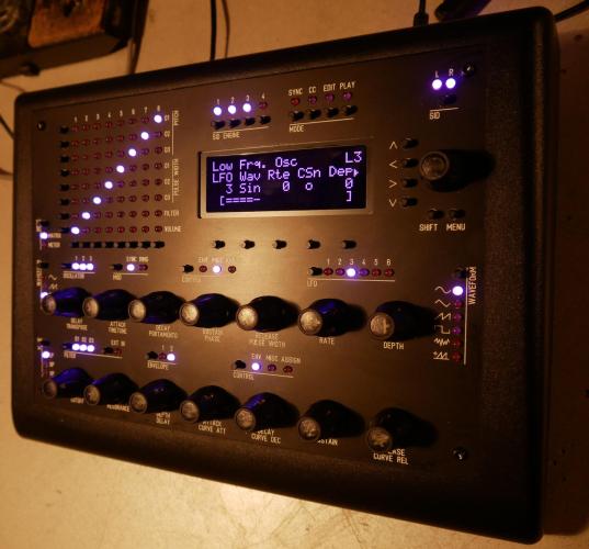
[S] BLM16x16+X
in Fleamarket
Posted · Edited by Phatline
new price 750€
i combined and wrote the 32bit Code so it now can comunicate with a SEQV4+, and off course with the SEQV4 standard, here is the sourcecode + firmware:
BLM_V01.7z
see also this short video (german):