

Zam
-
Posts
625 -
Joined
-
Last visited
-
Days Won
26
Content Type
Profiles
Forums
Blogs
Gallery
Posts posted by Zam
-
-
Thorsten
It's fine, I don't need more.
My only need is to know the 10bit value for a specific fader position to edit the table.
I have the formula, and I will try your code to have a direct reading in MIOS in place of PB value
On my side I will instantly visualize the change when monitoring the audio level, no need for other tools
Hope I can load the fader tomorrow or monday, and giving you a definitive feedback
Best regards
Zam
-
Thorsten
I just have a quick test, here is my report:
I was able to generate the table without any problem
I understand (but I be wrong) that "cal_tables_only.hex" only change the table, but it reset the whole setting
Fader respond fine to the new table when monitoring position data in MF tool curve
Extreme setting for ex
my @x = (0, 765, 1023);
my @y = (0, 256, 1023);get the PID lost and fader have oscilation
but I don't think some one use so extreme setting
I don't try more than 3 point for now
As I say i'm in the middle of mixing session, so i'm not able to put my motor fader in the desk frame, I can't check with audio passing trough and some 10 or more value table
Now, one question!
How can I monitor the 10 bits value data used, i can only monitor 14bits PB value to take and record the point I need for my table.
anyway great job !
tks a lot man.
Best
Zam
---------
edit: i have my answer
done with openoffice calc and some brain burning :rofl:
pitch bend value (+/- 14 bit) (say A data)
then B=A+8192 (to have a 0 to 16384 as B data)
then C=(B/16384)*1024 to have linear scale from14bits to 10bits
result seem more than realistic so I hope I'm right ?
now with "C" I have a direct value to edit my table :)
OK now I write all this and feel stupide...
here is the one formula conversion... C=((A/16384)*1024)+512 ...
-
Ok, please try this firmware:
http://www.ucapps.de/mbhp/mbhp_mf_ng_v1_005.zip
Once installed, follow the instructions of this README.txt:
I will officially release this version if you can confirm that it's working at your side.
Best Regards, Thorsten.
Hey Thosten
I don't expect this so fast !!!! you are amazing
I'm in the middle of mix session, I'm back to you asap :)
best
Zam
-
Thorsten
increasing the MIOS_SRIO_UpdateFrqSet to 32ms result to intermodulation around 30hz (31.35 to be precise), of course way better than the 1ms/1khz. The "fundamental" pulse still there even 10us (i was able tu reduce a little to sensitivities at 5 with shielded wire). Usable at mixing process, but not when printing the mix so an easy solution to desactivate the SR with a single button is an option. How it is easy to ad button function that is not a part of the user parameter in MF_NG tool ?
Also I run long wire (60/70cm) as mechanical integration is not easy, I think now I can't go to my first route with the pcb at the back of the console, I have to go with shorter wire and find room closer to the fader modules. I have 3 cm free under the armrest, needed to remove fader and channel by sliding in this modular system. I will find a solution to put the MF PCB here, with easy remove system to be able to service the desk.
This hasn't been forgotten... but please be a little bit more patient.Before giving you any code I've to test it, because everything which hasn't been tested typically doesn't work due to unexpected reasons, especially when I'm doing changes in code that I wrote many years ago!
Of course !!! just give me (if you can and without any pressure at all) some time range?
----
ordinateur-de-zam:~ Zam$ perl -version
This is perl, v5.10.0 built for darwin-thread-multi-2level
(with 2 registered patches, see perl -V for more detail):smile:
There is no limitation, because the perl script will do the calculation work, the PIC will only process pre-made tables.Cool ! you are cleaver :rolleyes:
Best
Zam
-
No, totally wrong...
Without going into too much detail: this would work in MIOS32 projects where the SRIO is scanned via SPI, but it doesn't work on a PIC where the SRIO is scanned directly from the PIC via bit-bangning.
This is done each mS, the number of SRIOs doesn't change this.
And if somebody would try to reduce the timer period for the bit-banging routine, the PIC would be busy with scanning the SRIO, but wouldn't be able to do anything else (-> no motor control).
ok, tks to correct me!
So the question is, can I manage the shift register for touchsensor with MIOS32 if I use a 32 core (for button/led/touch) and PIC (MF) just for the motor ?
What is the actual SRIO max scan frequency in MIOS32? the idea is to have it way upper 20/20khz range.
Other option is to have an assigned button that switch the MIOS_SRIO_NumberSet between 1 and 0 when printing a mix.
MIOS_SRIO_NumberSet doesn't set the scan frequency, it sets the number of SRIO components modulo 16Which means: 32 % 16 = 0 -> no SRIO is scanned anymore, no noise... but also no touchsensor scans, right?
Of course, my mistake sorry, I mean MIOS_SRIO_UpdateFrqSet !!!
I set it to 0x20 (32ms) with improvement in noise, the slower detection response don't seem a problem right now
but you can compile in the terminal, right?(I don't use Xcode by myself, too complicated ;-))
Ho! if it's too complicated for you, I better forget this for the moment...
Yes I have success to compile, with the code you give me to copy/past in the terminal
I just don't know/understand what I do, but it work :p
----------
Now it's time for next step
can you help me with this ?
What I also could provide is a small perl script which generates a look-up table based on given points:
Build process would be:
- adapt and generate the table in/with the perl script -> this will generate an include file
- rebuild the mbhp_mf_ng firmware with a PIC assember
- upload the new firmware (.hex file) with MIOS Studio
The whole update process will take ca. 30 seconds... fast enough to try out various settings.
Required tools: perl (scripting language), gputils (PIC assembler), text editor
And if you would install "gnuplot" on your computer as well, the perl script would spit out a diagram with the calibration curve as shown above
I think perl is already installed with devtools on my computer?
also a working gputils as I was able to compile with your terminal command.
How many "given point" can we use? if possible 14 should be good.
lets say 0-5-10-15-20-25-30-35-40-45-50-60-70-cut
I will made new measurement for respective PB value at both side, fader DAW and analog fader
----
Also i just drop some update about analog side accuracy i'm able to reach with new setup.
I'm less than +/- 0.5 dB between automation rec and automation play
I'm around +/- 0,05 dB between two automation play (audio recorded two time trough automated fader, with phase cancellation test)
The system miss shoot with 1 dB accuracy from the automation print, but always miss shoot the same with 1/10dB accuracy
it's in the 1mm range! i'm close to the 1024 step in 10cm fader, i can't do better and I'm happy with that :smile:
Best
Zam
-
hello
I try again to compile trough xcode without succes :(
Zam
-
Man !!!!
It work :rolleyes:
HUGE improvement in audio noise, this f... 1Khz noise go away
I still have the shift register 10us pulse clicking in audio (my PSI monitor are so efficient revealing fast transient), but as I lower MIOS_SRIO_NumberSet to 32ms (0x20) the intermodulation go down to 31.25hz in place of 1K, so just become inaudible
back soon
Zam
-
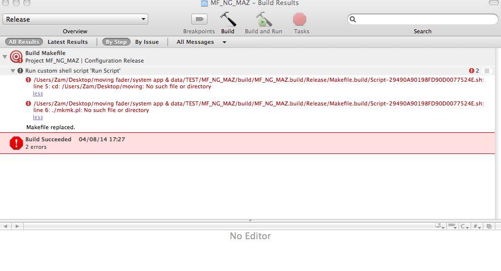
If you are not able to execute the Makefile, try to execute following command in the mbhp_mf_ng_v* directory directly:
gpasm -p p18f452 -I./src -I ./include/asm -I ./include/share -I ./modules/app_lcd/dummy setup_mbhp_mf_ng_standard.asm
Best Regards, Thorsten.
hello Thorsten
tks for help
10 min to understand why terminal answer me "No such file or directory" when I send cd command... it need a space after...now you have my skill level :sad:
I was finally able to execute your command, seem to work, I have a new .hex (regading the info date) also .cod and .ist
I will try to change MIOS_SRIO_NumberSet number
--------------------------------
Now some question to be sure I understand correctly.
MIOS_SRIO_NumberSet is the trig clock from PIC RD4 right? so if I increase to let say 0x05, my noise frequency should go down to 200hz (5/1000sec) ?
MIOS_SRIO_UpdateFrqSet is the time the shift register take info ? it determine the touch response time to standby the motor right? here we have 10ms
Now, were is the parameter (if one) who set the master clock used by MIOS_SRIO_NumberSet?
What can I do if I want MIOS_SRIO_NumberSet to be 0.05 ms (20kHz) or better 50kHz/0.02ms
Best
Zam
-
I'm f...ing lost in the programming side
I just try to compil by myself (as a training) the basic mbhp_mf_ng_v1_004 (without touching any code), I just have few day reading all I can on wiki and install tools
I'm so lost, that I don't know where to start to tel my situation, I feel so stupid...
I just want to change MIOS_SRIO_NumberSet in the main.inc file to test different touch sensor pulse regarding my noise
Zam
-
Hi Novski
No pb
actually I reduce around 220u (two 470 in series)
I made a new proto front panel in 3mm alu, it also improve mechanical noise.
I redone wiring with separate shilded cable for the 3 functions
servo, motor, and sensor
the servo 1kHz still there in my audio path :( I'm out of idea.
I think I read somewhere here, about grounding unused servo output and/or sensor
can someone confirm ?
best
Zam
-
Hi Zam I still didn't had enough time to check that. What im wondering is how it is placed because i dont think its a good idea to connect the minus of a pol-cap to the output of the motor. The voltage has to switch polarity to be abe to drive the fader back and forward. What capacity and volatge did you use for your tests? br, novski
hey Novski
that's exactly what I say previously, reverse voltage half the time, not good at all for definitive choices and long time use.
But it's a good start point test.
The best result I have is with 1000u (25v by memory) so to achieve the same with safety operation regarding reverse voltage you have to use 2x 2200u (10v is enough) in series with negative pin hooked together, so you have a 1100uF non-polarized capacitor.
I'm not at the studio, but will try a snubber RC filter soon.
Also an active integrator/low pass filter between pic output and H-bridge input, i saw this kind of design in later automated 990 studer desk
I just don't know if I can add a resistive load at the pic output, do you have an idea about this?
best
Zam
-
@novski
Did you try the capacitor?
@thorsten
I just instal Xcode and dev tool on my macbook
also gputils, and i saw perl is already installed
I don't find gnuplot compiled, maybe I can try to compile this to enter in the programming world ...
-
Where did you insert that Cap? Between +/- of the motor connections? I have to try this on my deaigns too!
yes between +/- but 50 cm from the motor pin at the other side of the two wire in my connection board.
1000uF polarized, not sure it's good with the time as it take reverse voltage in one fader move direction, better use 2 pces with negative pin together to make a big non polarized caps.
Global PWM reduced around 10-20. 0 is the best but with big caps you have jumping fader at the discharge
I also increase the motor voltage to 8V
It really improve the mechanical/acoustic noise of the PWM/motor noise, but target shoot seem less accurate.
Let me know your report if you test this.
I'm at a corner regrading my project, i feel your interface system really good, all the software side is so friendly with HUI/MCU.
But in the mean time i'm not happy with the motor systeme, PWM is good for DAW remote only, but not for fader passing real audio.
I don't know how flying fader© or moving fader© system are done at this stage, PWM or not but, for sure it's silent at analog side. Later SSL and other various automation use VCA so it's another world
I try to find a solution to convert the PWM into a nice variable analog DC signal, inserting big caps is the first step.
I want to try RC filter, but I find noting in the L293 datasheet regarding resistive load :(
Maybe I can try 10 ohm (with 1000uF for 15hZ cutoff), it's "just" twice the motor coil ?
I'm also looking for other motor driver able to output a smooth DC from the PWM
Touch 1kH trig still a BIG problem...
--------------
I think in just understand the slash/backslash\ and sine function in MF tool, and why faders don't reach the same target (at the same time)
As I have only two fader for my proto, result is not behind your eyes, this functions just visually show / , \ , and moving wave with 8 fader right ?
Best
Zam
-
ok it was just the 7805 thermal protection
I get interesting test with various big cap at -/+ motor, actually 1000uF improve the motor mechanic and electronic noise
Zam
-
Did you alredy tried to connect the shell of all Faders together to GND?
Yes they are, maybe not the best GND pass possible for the moment but thy are
-On the fader side the 0V servo is screwed to the front panel (get me better motor noise result), and the fader is also screwed to frontpanel so shell is refered to 0V
-As my console is modular each 0V and 5V sevo go separately to a daughter board for main 0-5v distribution to fader, 0-5V picked at J2
-0V is refered to GND at J11 with wire to chassis lug where I also attach main Earth
By the way I just short cut 0 and 5v at J2 by mistake when measuring other things
My fuse don't blow up (i forget to reduce it's value after first test...) something is dead , have 0V everywhere, hope it's not the PIC :( ,but just the 7805 or the bridge rectifier...
Zam
-
When you swap J2:A0 and J2:A1, you also have to swap the motor control outputs (J3 and J4)
It's a servo loop...
Best Regards, Thorsten.
Forget my previous post, of course I swap the motor too as each fader have a separate ribbon for servo, motor and sens...
so I have a problem somewhere!?!
--------
Another question come in mind,
Is it possible to add a resistive load in series with the motor?
I wana try a simple RC LPF filter to smooth the PWM
-
Thorsten
I'm still having trouble to reduce noise.
The 1kHz is very problematic (more than 10 dB louder than my noise floor with only one fader)
I try various cap around ground, noise disappear but sensor become active so...
It's not possible to filter this as it is the main data modulation, 1kH digital trigger is really not analog audio friendly
And the signal is electronically floating.
I ask anyway, is it possible to setup this pulse over 20kH, say 50kH to be safe? even if the PIC only analyse data every mS
I will try optimising wire now, It's the last thing I have in mind
As soon as I find solution for this, I come back for the software side
----------------------------------------
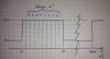
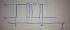
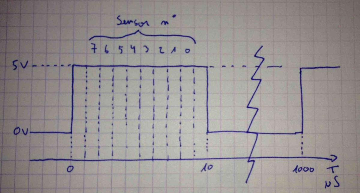
I have a look at the scope just to know and see how this works,
it's more a n*1uS where n=is touch sensor n°, with time distribution from pulse start +1uS
I attach 2 pict, second wave form is when sensor of fader 1,2,3 and 5 are touched.
-
When you swap J2:A0 and J2:A1, you also have to swap the motor control outputs (J3 and J4)
It's a servo loop...
Best Regards, Thorsten.
Of course... i miss that :p
My fault !
-
I was able to solve that shivering with grounding the shell of my fader and the Frontpanel properly.
I will try this. On my side the fader and front panel are well screwed, but at this location of the desk the electonic inside the fader module could be considered as floating, no contact to the frame. I have to manage this.
Today I reduce the voltage and find some compromise with new duty setup, also change the deadband.
Zam
-
I'm just thinking about another strange thing I don't understand.
When I hit slash and backslash button in MF Tool my two fader don't go to the same position.
I swap the fader at J2 and it don't folow, but stay at the same PIC output???
Zam
-
What kind of desk is that?
my lovely Studer 289 :smile:
--------------
Thorsten, what you could provide sound good to me, i think it deserve a try.
As i say previously I'm new to programming, I already install X11 on my laptop, and will instal dev tool,
I need time to be efficient at this task (learning the tools), but solving this problem and find the good solution could really open a new world for all ple like me using old desk, I already have two friend/studer x89 owner folowing my modification.
I will look closer and download the tools.
I keep you informed about this.
It's a pulse of n*1 uS (n = touch sensor sensitivity value) which is triggered each mSI'm unsure if/how this could be filtered. You could start with caps against ground at pin #27 (RD4) of the PIC (this is the pulse output)
Best Regards, Thorsten.
I have a look at my noise frequency, it's 1K (and harmonics 2k 4K etc...) so it's the 1ms trigger for sure.
I wish It will be some subharmonic artefact I can filter, but it's not, and it's in the audio range :(
I put a 100n across 5V and 0v at the J2 (like in MF V1) but without success, I will try your suggestion.
I have to investigate more (disconnecting the touchsens ribbon sound worst...), it's also could be a fader design issue, audio, servo, and touch track are close...
Zam
-
-
Hello
some update
I connect and run the two fader I show before, and perform more test and calibration setup
Good new is now I can say only one hard coded(fixed) table for all fader is need, fader tolerance are good, no need for individual correction, and I'm using cheap ALPS, will be better with P&G or TKD
I still have problem regarding noise.
Now I connect each 0v servo to individual module enclosure, it's better for motor noise in audio, but I wish It could be even better. Grounding and ref voltage is not easy when interfacing digital device in a large analogue desk, I have to try different grounding.
Other one, way louder and problematic, is noise produced by touch sensor. When I touch the caps it become quieter, and close to silent if I touch my console frame at the same time. If I set sensor sensitivity to 1 (minimum) noise disappear, but fader is not usable at this setting.
I don't record frequency yet, but sound like fraction of the digital clock. What kind of signal is use for touchsensor? just DC? do you think I can filter this with some LPF to avoid HF leaking here?
regrading fader move i'm not 100% happy with settings I try, I like the fader fast when I read a square automation. But I can't in the mean time stop the fader knob to have crazy shake when reading a slow sin wave automation.
Zam
-
Ah, you are using the MBHP_MF_NG module standalone (without a MIOS32 based module where MIDIbox NG could run) - in this case forget my idea.
No I don't forget your idea :smile: at the end I need button and led so I need a core system.
This would require an interpolation routine which consumes too much CPU time on a PIC, especially when multiple faders have to be handled in parallel.In order to overcome the execution speed limitation, somebody would typically precalculate tables based on these "points" and store it in RAM... if enough would be available.
The 0, -5 , -10 etc... have direct and linear correlation with DAW fader pitch bend value at one side, but maybe you talk about "interpolation" between this points at the other side? which is not linear but like one of the graph I post before?
-----
All this is just to have an efficient grouping fader possibility that track well at the analogue side...maybe i'm too ambitious :sad: and don't have the skill to build (program) what I want. Or the system can't handle this in any way? is that you saying?
I understand you are not interested on this, and by the way, I don't buy you a beer :tongue:
Best
Zam

Upcoming MBHP_MF_NG module
in MIDIbox HUIs
Posted
hello
sorry for the delay, lot of work at the studio
currently testing the new table tool with the fader loaded, it work :)
I will give more feedback this evening, when I optimise my table
Zam