

niles
-
Posts
40 -
Joined
-
Last visited
Content Type
Profiles
Forums
Blogs
Gallery
Posts posted by niles
-
-
Hi Andy and Peter -
Got a weird bit of behavior from encoder #9 and looking to see what your recommended steps to diagnose would be. The encoder is showing some weird behavior - pressing it works and registers, turning it while it's pressed registers, but just regular turning it doesn't work. Sometimes after I press it it works a little bit like it's skipping around but mostly it's dead unless I'm holding it down and turning it at the same time. Encoder went bad do you think?
Thank you
-
On 9/2/2019 at 0:36 PM, Hawkeye said:
@niles unfortunately, not all MIDI USB OTG gear seems to talk well to each other.
For example my (older) AKAI MPD24 works perfectly via USB with the SEQ, but my newer, small-keys midiplus x4 mini keyboard (which looks a bit like the keystep) does not yet work.
It think there might be a software/communications handshake issue with some newer USB MIDI gear - which has the advantage, that it might be fixed at some point in time, if someone has the time to look into it.
Best regards,
PeterHmm..that is good to know. Could be my somewhat modern gear - although the SL Mk2 is pretty old I think. Thanks
-
12 minutes ago, latigid on said:
Shouldn't need a special cable, but to be honest I've not played around much with the OTG stuff. Did you route the MIDI anywhere, set the channels up etc.?
For some instruments with Midi DIN I have, but shouldn't I at least see some activity on the midi monitor under USB1, USB2, USB3, or USB4 using a usb keyboard?
-
That is awesome progress/news on the cv modules, very cool stuff! Got a quick question that I guess is more troubleshooting related than operation related -
On the Midi IN4 and OUT4, I know they are planned for controlling the BLM at some point in the future, but in the meantime should they work as regular Midi in/out ports? I have a keystep plugged in and it works on IN1, IN2, and IN3, but not 4 (when viewing via midi monitor). Was curious if it's a midiseq software setting or intentionally hardwired to be different.
My vote goes to bad wiring on my part, but just double checking.
Thanks
EDIT - Actually the more I read on the USB OTG it seems like I should be able to plug the keystep into USB with the switch in the OTG position. Quick power cycle but still no activity on the midi monitor. The same if I try with my Novation SL MK2 midi keyboard. Both they keystep and SL are being powered by a PSU and not reliant on USB power. Do you need a special OTG cable for it to work?
-
3 hours ago, Hawkeye said:
much i would change, no - recommend to go for 8580s and omit the fan, go for an OLED or a VFD as a display, a better PSU and a 6.3mm direct mix out, but the rest was just pretty perfect from the start :).
Many greets and have fun building it, it's a great synth!
PeterMany thanks, Peter. I got a deal on 8580s from meeblip awhile back, I'm working through PSU option E. Got an OLED screen. I'm thinking of panel mounting the switches directly above the window so I can flush-mount the screen. Probably just build my own enclosure, it looks pretty cramped in the PT-10 and I like a little more room to work with. Based on your one post about how much of a pain the flat leds are I'm thinking of just going with regular round ones.
The PSU is tricky for me since Jaytee's build guide leaves off necessary components from the original Wilba build guide, which makes sense since its original intention was a retrofit but a little confusing for scratch builds. I think I can figure it out.
-
Lucky 13! Thanks, @Hawkeye!
-
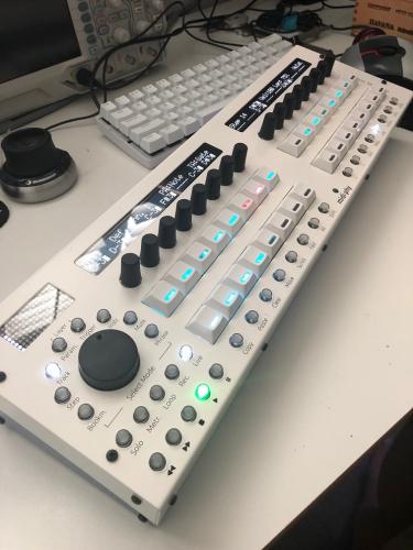
All working now - Here's my beauty
 Turns out I had a bad cable (my nemesis) for the MIDI8 board.
I went with the red/cyan color mix for the LEDs. Keycaps courtesy of @Antichambre . Also, I went with shorter 16mm keycaps for the switches ( mouser 642-1S11-16.0 ) instead of the 19mm from the BOM, I thought those were a bit too wiggly. I had a few self-inflicted hiccups along the way but I'm extremely pleased with how this turned out and the quality and support of the midiphy kit is top notch, of course.
Cheers!
-
On 2/25/2016 at 1:36 PM, Hawkeye said:
JB-Weld itself also is only strong, when the surface area is not smooth as a newborns behind :-), you definitely have to sand things, to get some "rough grip area", but even then, I am also not totally convinced by the stability. If a new panel was built, I'd probably go for some countersunk screws on the frontside, spacers and screws on the bottom of the CS PCB, just like you did!
You wrote this kind of a long time ago @Hawkeye but can I ask why did everyone used JB-Weld in the first place vs just having screws from the top? People didn't want to see the screw heads on top of the panel?
Why not use the encoders to attach the front panel? Looks like there is room to lower the panel a few mm - was the height dictated by the original LCD height?
Apart from the flat-top LEDs being a bit of a pain, anything anyone would do differently with their build? I've read all the big threads and really studied the wiki pages. Looks like an exciting project!
-
Latigid on and Hawkeye - THANK YOU! It's up and running! (one caveat below...) Sorted out my JA board issues and it's firing a basic sequence now. The OLED displays are amazingly crisp and clear. This box is a thing of beauty, really quite a nice piece of engineering and design. I am looking forward to learning it. Thank you for offering it as a kit!

One caveat, though (there's always one in my world), is that I'm getting weird output from the 4 main Midi out ports. To test it I'm running a simple sequence with one note and one default gate length, and my synth gets the note (a behringer neutron) but only once ever, and it's like an infinite gate. Happens with all 4 of the Midi out ports. The IIC ports all work great when I change the midi output port on the fly while the same sequence is still running. The IIC ports appear to be operating normally so I'm thinking it's an issue with the midi8 board.
Before I tear it apart and examine the midi8 pcb, I just wanted to confirm that there's no global setting or something that I need to enable or set for midi8 board? I'm guessing no but hey just double checking.
If I do need to debug midi data, is there a recommended method or test sequence I should run against a known good port? Should I use mios studio or midi-ox or probably doesn't matter?
Thanks again
-
On 5/26/2019 at 2:44 PM, niles said:
Thanks - I think it's the cable. I have continuity everywhere but from J5 pin 8-> cable-> j2 pin8. Will replace that once I get new ends - I think I wore out the 24pin header.
Just reporting back in quick - it was the cable. I guess practice makes perfect, now the led matrix works perfectly. Getting there :)
-
@SimonSays Please keep us updated since I also ordered the PCBs from modular addict awhile back. I'm hopefully finishing up my seq v4+ build soon and will tackle a 6582 build soon after. Got a small bonus at work and splurged on a slew of 8580 chips from meeblip a few months ago in preparation, also. I guess they are sold out now.
Have you turned up any ideas for the display? The hot thing is OLEDs now and some people get them to work it appears, though I haven't found a real guide.
-
On 5/25/2019 at 1:59 AM, latigid on said:
The JA matrix is driven by the extra ICs on lemec_R. The fact a whole row is missing points to an issue on the sink side.
Check continuity (also for cold solder joints and faulty cables) from the following pins
lemec_R:
IC17 pin 1 :: IC18 pin 7
IC 18 pin 12 :: J5 pin 8
J5 pin 8 ::IDC cable to JA:: J2 pin 8JA:
J2 pin 8:: MATRIX pin 14.The matrix pins are labelled like an IC, so anticlockwise from the bottom-left dot.
Thanks - I think it's the cable. I have continuity everywhere but from J5 pin 8-> cable-> j2 pin8. Will replace that once I get new ends - I think I wore out the 24pin header.
-
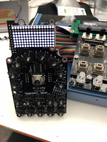
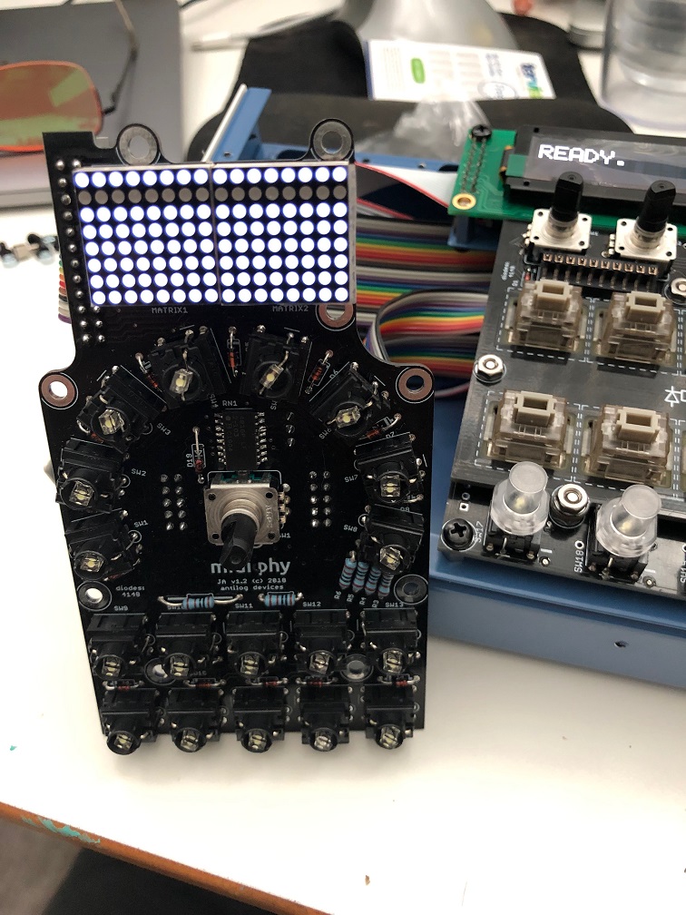
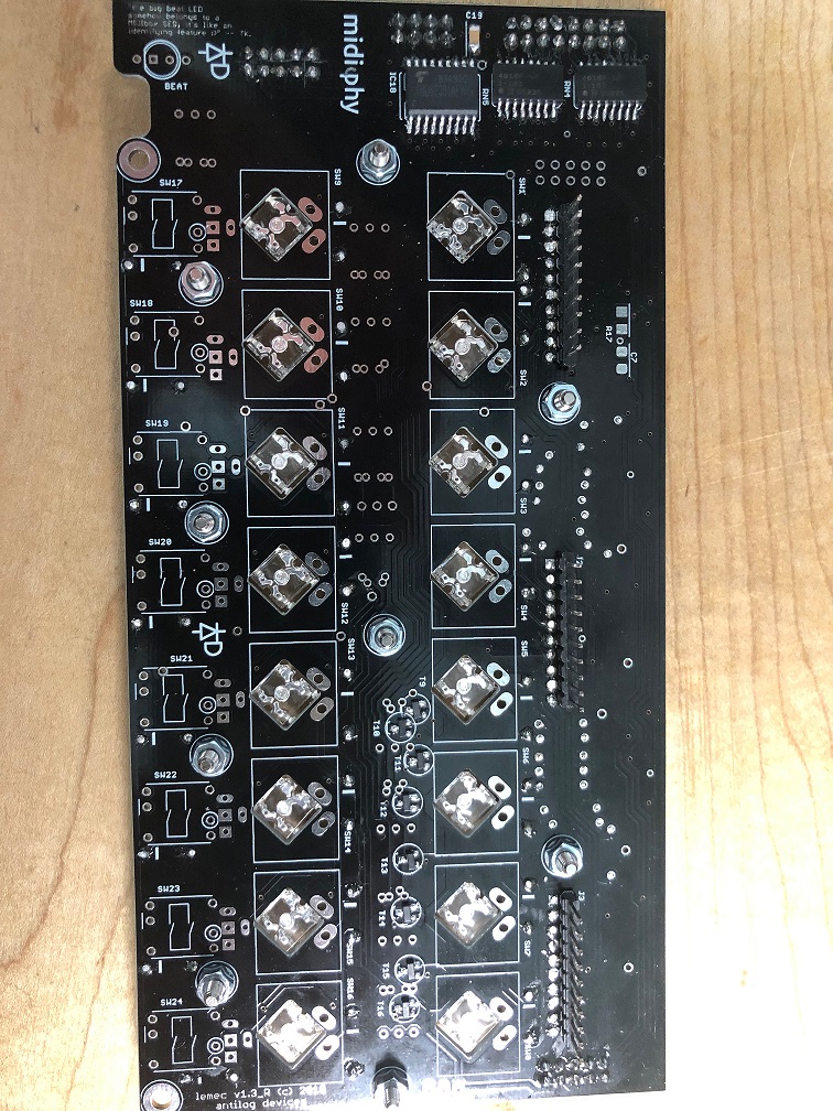
Hi - I had some more time today to make some really good progress. So far everything is going smooth except for the JA board. I have the case almost all the way together. for the JA, I'm going to debug the weird button behavior I had way back, now that I know how the ICs work a little more. Anyway do you know what would cause this row not to light in the matrix (please see photo below)?
The 2nd row of 16 leds aren't lighting on the JA matrix. I've reflowed the matrix pins and the large 24pin connector, as well as the respective connectors on lemec_r. I am guessing this matrix doesn't connect to anything else on the JA board that would cause just this row to not light?
Thanks
-
20 hours ago, latigid on said:
Frequency is controlled by the CPU, I'd say if you see the clocks at all it's good. It might be that RC is 1 kHz.
How's your DIN matrix looking?
Makes sense, I suppose it would want to go as fast as possible for quick registering. Is the RC = reset clock?
Still not seeing any action on switches. I did for a little time right after I reflowed the ICs I mentioned but now nothing is showing up in MIOS. I'll test all the pins again with the scope and report back and basically go back through your previous posts on this thread. I still get perfect encoder twisting registering in MIOS studio, just no switches.
-
On 5/6/2019 at 2:24 PM, latigid on said:
Perhaps the serial data doesn't make it to IC2. Actually ICs 17, 19 and 20 are before IC2 and finally IC4 in the chain. Scope the same pin 14 on each IC to see how far it gets.
Initially I wasn't seeing anything on pin 14 on IC20, so I reflowed 17, 19, 20 pins and now I do see something. I do see normal (I think) behavior on IC2 now. I am curious what the CLK signal should be, though. You mentioned 1khz. I'm reading a little over 667khz on all clks, including the left le mec board. Thinking it was user error, I tried my function generator with a 10khz square wave the scope read it perfectly with no adjustments. I am wondering if perhaps it's just getting clk'd too fast to really give reliable operations? What controls the frequency signal?
-
13 hours ago, latigid on said:
Check R26 is properly soldered and that pin 13 of IC2 is ~0V.
I believe it is, what is the side of R26 connected to? I see the end closest to the pcb edge is to pin 8 of IC2. I thought I could test resistance between pin 8 and the mystery point just to be sure R26 is soldered on there correctly.
Turns out there is no pulse train on Pin 14 on the R board. I see it clearly on the L board, it does help that one board works to compare! Do you think this IC2 is just a dud or perhaps damaged somehow? I get 0V on pin 13, also.
-
23 hours ago, latigid on said:
Restart MIOS studio and don't load an NGC file. If you can be careful enough, you can try bridging the 165 inputs to 0V one at a time.
I tested it this way and saw only one note at a time when I bridged those 165 pins to 0V. Also I see the same behavior with the seq-plate removed so I don't think it's a clearance issue.
On 5/4/2019 at 2:25 PM, latigid on said:Pins 11,12,13,14,3,4,5,6 of a 165 shift register are the inputs. If you don't read a voltage, probably the contacts in the encoder are connected to the common (0V) pin. Turning the encoder will change the state of the 165 inputs. You should also test the switch behaviour on IC3 in this way (first column pin 11, eighth column pin 6). I.e. test a switch in column 1, check that the input on pin 11 toggles low and high again. Check that the other inputs do not toggle.
On the L board, I see a sequence of 1 square wave that drops to 0V, and holding down 2 switches I see 2 square wave seqments drop to 0V so I assume that is all good. On the R board, there is no sequence(?sorry I don't know the correct term) drop to 0V, it's the whole thing, just all flat to 0V. Same with the other columns on the R board.
I checked, no shorts between pins on ICs.
On 5/4/2019 at 2:31 PM, latigid on said:With the NGC loaded, with your scope you should see the 595 outputs on IC3 (pins 15,1,2,3,4,5,6,7) toggling high in a sequence of 8. The pins correspond to
A B
C D
E F
G H
where A controls the first four encoder switches, B the second four encoder switches, C the first four Matias switches...G the first four MEC switches (note SW19!)...
With seq_r loaded, on the Left board, on the scope I see a sequence on each of the output pins of IC2, although I can't seem to see any activity even if I press the switches. They just seem static although that could be my inexperience. I mean, the Left board switches still register in MIOS studio console so it's prob me :) On the Right board however, each of the outputs of IC2 are reading high, no sequence. That would probably make sense that IC3 has all the high readings, then, right? If it depends on the outputs of IC2 being correct sequence?
Both chips have clock in, it appears.
Hopefully I'm still moving in a forward direction with this!
-
11 hours ago, latigid on said:
Are the note events always the same, no matter what switch is pressed? I can't see any of the parts designators, so I can't help there. It's a bit fuzzy, but the solder joints look rough rather than smooth. So maybe some cold joints are there. Maybe try a slightly higher iron temperature?
The JA board not being connected doesn't affect things.
Are you sure you have seq_r.ngc loaded?
As you have a working le mec, you can compare voltages on IC2 and IC3. Note any differences.
Well for each button pressed it's the same each time. I get different groups of 4 registered in the debug screen on each encoder. Now I can't get any of them to register, unfortunately, after a good cleaning. Encoder twists still register great.
COnfirmed I have seq_r.ngc loaded.
I started comparing lemec L and R, and on IC1 on the L board, I don't see any voltage on pin 4 and 6, although I do on the R board. My L board is working fine (switches/encoders that is), should pin 4 and 6 read +5V as on the R board IC1? IC1 is right next to the J89 connector on the Left board, so wasn't sure if maybe that is relevant to my problem.
I'll continue comparing the IC voltages via my scope but just curious which ones should be the same between L and R. All of them?
Thank you
-
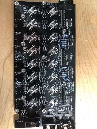
pretty sure everything is correct, I can make another cable (third one...) and see if that makes a difference. In the meantime here are photos.

-
9 hours ago, latigid on said:
At a guess, some of the components from the seq-plate are shorting out those on le mec. The usual offender is the encoder right above the J89A header, but it could be more around IC3 on le mec, e.g. long diode legs from above.
Check the diode orientation too.
The note numbers from your output can be used to trace events in the NGC:
D#2 = note 39
D#4 = note 63
D#6 = note 87They correspond to the fourth column of buttons, pin 14 of IC2. Check the sixth pin (counted from the left when looking at the top of the seq-plate) of the 10-pin header J2.
I get a similar output each time I press any of the encoders on the right lemec board, not just the ENSW8. I don't see anything touching, and I see the same behavior if I swap seq-plates from the left lemec board.
As for SW19, when I temporarily install all the switches in the lower row, each switch registers similar 'quadruple' output messages as the encoders. Same thing happens if I test SW1->16 as Peter shows in the video with a small, horseshoe shaped length of wire.
I reflowed some points and all the diodes, still no luck, unfortunately. Given that it's happening to all switches, would there be a point somewhere that would affect all of them somehow?
Also I don't have the JA board connected past the right lemec so not sure if that is affecting things?
-
@SimonSaysWow great job! I am getting there bit by bit myself.
I am at the DIN switch test phase, I have the lemec boards plugged in and since I hosed my JA board I have the Left lemec plugged into the core and running seq_r instead. The left board is checking out good so far. The right lemec's encoders register normal when I twist them, but pressing them as a switch registers 4 events. All the switches on the right board register as 4 different switches, I assume the ones in their little matrix. The bottom 4 (SW17, 18, 19,20) do not register at all. Any idea what this could be?
Sample output when I press ENSW8 on right lemec:
[130673.482] 90 4b 7f   Chn# 1  Note On  D#4  Vel:127
[130673.495] 91 63 7f   Chn# 2  Note On  D#6  Vel:127
[130673.500] 90 63 7f   Chn# 1  Note On  D#6  Vel:127
[130673.515] 90 33 7f   Chn# 1  Note On  D#2  Vel:127
[130673.618] 91 63 00   Chn# 2  Note Off D#6 (optimized)
[130673.622] 90 4b 00   Chn# 1  Note Off D#4 (optimized)
[130673.636] 90 33 00   Chn# 1  Note Off D#2 (optimized)
[130673.640] 90 63 00   Chn# 1  Note Off D#6 (optimized)
Thanks
-
On 4/26/2019 at 5:42 PM, latigid on said:
Hello,
For testing les mecs, you'll want the seq_r.ngc.
The easiest place to test for power is on the J14 three-pin connector on the east side of the board. 0V in the middle, +5V above (marked with the silkscreen). Always test that these pins aren't shorted together before applying power. The other pins I've already mentioned I think. The voltages will depend on the speed of your multimeter and would be best viewed with a scope.
For 595 chips: pins 16 and 10 = +5V; pin 13 = 0V (resistance may be 10k).
For 165 chips: pins 3-6, 10-14, 16 = +5V; pin 15 = 0V.For J89 header, pins 1,2 = 0V, pins 3,4 = +5V,
Thanks!
-
@latigid on Hi I'm at the point of testing the lemec boards, and if you recall I have some issues with the JA board. As you suggested earlier if the power is ok, at least some of the board should work. I just want to make sure power is ok passing through the board, could you let me know what the voltages should be on the pins for SRIO out? Or point me to a link with it, I can't seem to find it via search. Thank you!Nevermind I forgot I can use seq_r to just chain it the other way around. I'll figure out the JA board later. Thanks though
-
On 4/13/2019 at 1:43 AM, latigid on said:
To me, the board would benefit from reflowing all pads, maybe with a bit more heat, perhaps cleaning the flux off especially around the ICs.
Will do.
On 4/13/2019 at 1:43 AM, latigid on said:No problem, just choose the _R.NGC when testing. In fact, I would suggest chaining JA -> le mec_L to see if the SRIO makes it out of the JA. As long as the power rails are okay, nothing else should happen. If le mec works as intended, then at least some of JA is fine.
That makes sense with _L vs _R chaining order...I'm going to give your suggestions a shot, the piano roll on midi channel 3 with seq_l.ngc loaded and the chaining test. will report back once I have something.
And as always, thank you for the thorough reply!


Troubleshooting midiphy SEQ v4+
in MIDIbox SEQ
Posted
Awesome...I'll start there - thanks for the fast reply!