

John_W._Couvillon
-
Posts
350 -
Joined
-
Last visited
Content Type
Profiles
Forums
Blogs
Gallery
Posts posted by John_W._Couvillon
-
-
Do I understand you correctly? All you want to do is strip out the "innerds" of the old Hammond, except for the on/off/vol knob,and use the cabinet for some other purpose?
You say you want to convert it to a midicontroller, which is very general, and very confusing. To do what?
Exactly what are you trying to do that you need a midicontroller? Are you referring to a midibox core 8, or an LP-17 core, or a 32 bit core? What is the midi controller supposed to do?
How do the 3 keyboards you already have enter the mix.
Need some help.
John W. Couvillon
-
Johannus OP240.,
Have you constructed the control surface? Take a look at the writeup for the midio128V3. it specifically covers the analog programming using the AIN module and others and how to program it.
Johnc
-
Johannus OP240.
If you are discussing mios8 and midio128, you are in the digital domain, not analog.
What are you attempting to do?
If you go to the Ucaps website, and go to the link for MIOS8 located in left panel, you will find some apps down at the bottom of the list dealing with J5.
johnc
-
Pharline,
I think you best bet to use the reed relay approach that is described on the midibox website. That way you will get the o imped. connection.
johnc
-
Tom,
If the organ is to remain intact and fully playable, then all existing relay functions must remain. Adding midi in and out means:
The existing organ relay would have to be modified to accept a midi input stream, and also generate a midi output stream. Accomplishing that brings up many questions, and could be done by several methods, i.e.
a. Modify electronically the existing relay to accept the midi in and out, which could be difficult or impossible depending on the design of the relay.
b. overlay, mechanically, the key contacts, stop action switch contacts, pistons, swell shoe, such that the mechanical switches operate a second set of contacts that are inputs to a midi system of DINs, KB boards, LPC17, etc., and a PC running jOrgan or Haupwerk which would serve as the midi relay, generating a midi out stream. It is also possible, if not preferable to output the midi stream directly from the LPC17.
c. The third possibility would be to gut the console and existing relay, and replace it with a new system of midi devices which would power the pipe palet valves, and SAMS ( if you have them). This would be by far the most costly, and complicated.
Of the three choices, I have done choice b, and c. In one case with a pc running jOrgan, and the other with an LPC17. Both installations provided a standard organ system, no monitor, mouse etc.
You continue to talk about DINS, DOuts, LPC, but its not clear how you intend to apply them. Does any of the choices match your intent?
Concerning the midi in and out, Do you intend to play midi files recorded on computer based software? Do you plan to play on this organ, recording internally the midi messages, then play it back on this organ, what is your intention? All this has a bearing on the hardware and firmware as well.
Who built the organ? does it have SAMS rocker tabs or pull tabs, set button and gen cancel, combination action by peterson, Syndyne, etc.? Does the combination action have memory? Does it have a relay cabinet separate from the console, or is the relay internal to the console?
I will keep going with this, if you could answer my questions.
johnc
-
Hello TOM,
You are embarking on a project that has been explained in depth many times on this forum. Your statement, " Goal is to have MIDI IN and OUT for a church pipe organ (2-61 note keyboards + 32 note pedals + Stop Action switches)" is sort of open ended, allowing a variety of outcomes. In order to have a better understanding of your Goal, a few questions>
1. As stated, the instrument is a pipe organ, "pipe" being the key word, and its a two manual instrument with pedals and "stop action switches".
> How many ranks?
> Will the midification replace the existing organ relay, and is the relay integral to the console? There are a variety of small 2 manual consoles (Moller Artiste, 3-5 ranks for example) without a major relay, but a mechanical system where the key switches activate the pipe pallet valves electrically. Your course of action is dependent on your intentiion, i.e., do you intend to gut the console and replace with midibox encoders, etc.; augment the existing to allow addition of pipe ranks, or electronic, sample based ranks, or to leave the console intact with a midibox overlay to provide a functioning virtual organ, computer based, using jOrgan, Miditzer or Hauptwerk virtual software, yet still have the option to play the organ in its original form. How you apply midibox DINs and DOUTS and the midio128 V3 app will depend on where you are going with the project.
2. "stop action switches" imply manual rocker type switches mounted just above the top keydesk, Is this the case, or, are they SAMS, with a set and general cancel button, and combination action?
3. You need to read the specification for midio128V3 in the UcAPPs section on the midibox website. midio128, v3, will provide 128 inputs and 128 outputs Using groups of DINS and DOUTS, which could be enough to midify your console, but again, that depends on what you have, and what you want to achieve. You are not necessarily limited to 128 i/o, because of the capability of using KB matrix modules of which you could have several increasing the inputs and outputs. for example, I am running a 3 manual console with pedals, 64 SAMS with combination action (Peterson). The console uses 2 KB matrix modules to encode 3 keyboards, pedalboard and the stop contacts on the SAMs. This freed up the 128 std DINS (DIN4X) for pistons, etc., swell shoe s and cresendo pedal. My organ is totally electronic, no pipes, and uses an LPC-17 and an additional Core8, an Artisan Sound Engine with artisan Samples. I designed it to be free of a PC, and virtual organ software (jOrgan, Miditzer, Hauptwerk) with touch screen monitor, etc.
You also need to look at the newer "NG" software which can do everything that the midio128V3 can do, plus more.
I will be happy to answer any question you may have, or point you as needed. in addition, there are many who have walked the path you are on, and will through in comments as you go.
My suggestion at this point, is for you a be more specific in what you want to achieve in the end.
Johnc
-
Phatline,
Can you elaborate on your electronic organ; type, electronic encoders, etc. when you say "midificate" thats not quite enough for objective understanding. some interpretations could be:
1. you strip out all existing internal electronics and install key switch encoders DINs, a midibox core device (core 8, Lpc17, etc.) runnning midio128 or other. using a pc for relay operations.
2. You only want to force the existing organ to play by, in effect, forcing keys down electrically rather then by finger.
I assume "kepresses on ground level" means the contact actuated by the keypress is grounded on one side such that the input to the key encoder goes to ground.
How are you attempting to midify the existing system? Are you trying to parallel the two systems by signal input from the key switch contacts, or, are you trying to force the voltage on the key switch input to the existing system.
As I read your words, it sounds like you are attempting the later, applying a short across the key switch contact by having the output pin of the 595 go from 5vdc to 0. I would think that the suggestion to invert the action of the dout ( reverse the output voltage swing from high output when on, to low output when on).
As a alternate you could add ULN2003's or ULN2803s (/quad. drivers) for all outputs on the douts, and parallel the output contact of the uln with the keyswitch contact. With 0vdc at the output pin of the 595, the voltage of the output on the uln would be supply (cold be 5vdc) with 5vdc out of the 595, the ULN output would go to zero. This could work provided it doesn't screw up the existing key switch encoders.
You could also drive small relays with the 595 with a relay contact shorting the keypress contacts.
Again, what are you trying to do overall?
sorry I can't be more helpful!
Johnc
-
My interest is up in the area of driving stepper motors for CNC projects, etc. Stepper motors can be driven with Arduino, RasbPi, etc using a uln2803 quite easily, so can't see why a core 8 couldn't be used as well.
What existing app for the core8 would best be adapted for this application? midio128 V2?
Does anyone have experience in this area, and is willing to share?
Johnc
-
TK,
No, you are not lost. I was not aware that the behavior of the status LED had changed with ver. V3.019. That explains the situatiion most adequately.
Thanks,
johnc
-
I hope that I explained the situation commpletely.
The LED has always blinked and stayed on especially when first energized, but it has never been this bright and pulsing on and off. This behavior began when i plugged in the USB cable to use mios studio. The LPC has been operating along time with a core 8 on a common power supply, so the jumper isolating the system from usb/computer power was removed.
since the incident, returning to USB power with the jumper in place does not solve the problem.
Also, the reason I was using mios studio was to load the recorder/player fix that you (TK) provided to correct some code issue involving matricies. the "fix" did get the recorder working (I thought), but all of a sudden, strange loud fixed pitch sounds came through that are not related to the material being played back. I had to pull the power to the LPC to clear the noise. Now I question the "fix"!
Johnc
-
The red LED on the LPC pcb is cycling on and off, slowly building up to bright, then fades away. the LED cycles much like the led on a USB flash drive. The LED is much brighter then normal at its brightest
The LPC has midio128ver3 loaded and appears to be functioning normally, with exception of the LED.
This began when a USB cable was plugged into the USB connector on the pcb to view the DI settings with mios studio. The unit was energized, receiving power from a 6vdc supply (J1), and the jumper on the PCB (J22)was removed to isolate from the USB power source. The usb cable was removed, jumper inserted and the unit reconnected to the 6vdc supply, and the LED still cycles.
Is it a NO, NO to do the above, and is there a way to recover?
Johnc
-
Pete, I plan to use a 3/16" panel, and yu read my mind. The SD reader will mount on a wood block glued to the back of the panel. When the sd card is in the reader, about 1/4" sticks out, so it should fit perfectly. The pushbuttons, LCD and encoder switch will also be on the panel.
Thanks for the input.
johnc
-
Hi Pete,
Thanks for the input. Google brought up several sources. The style I am looking for is of the type sold by ESS, http://www.esskabel.de/upload/files/pdf/ADA-SDCARD-USB_EN.pdf. Only problem is that it adapts to USB. There is also one similar to the sparkfun unit available from Parallex, but has no angle bracket to mount the PCB at 90 deg. to the face of the vertical wood surface.
Johnc
-
Anyone,
I want to build the control midio128 V3 control surface into the face of my organ console with a card reader mounted behind a slot in the wood surface for insertion of the SD card. Does anyone know of a source for same?
Thanks,
Johnc
-
TK,
Great!
I assume the all I have to do is set up my PC, run mios studio, and load and transfer the hex file to the LPC, and I am good to go!
Thanks Thorsten, and you too, Pete!
Johnc
-
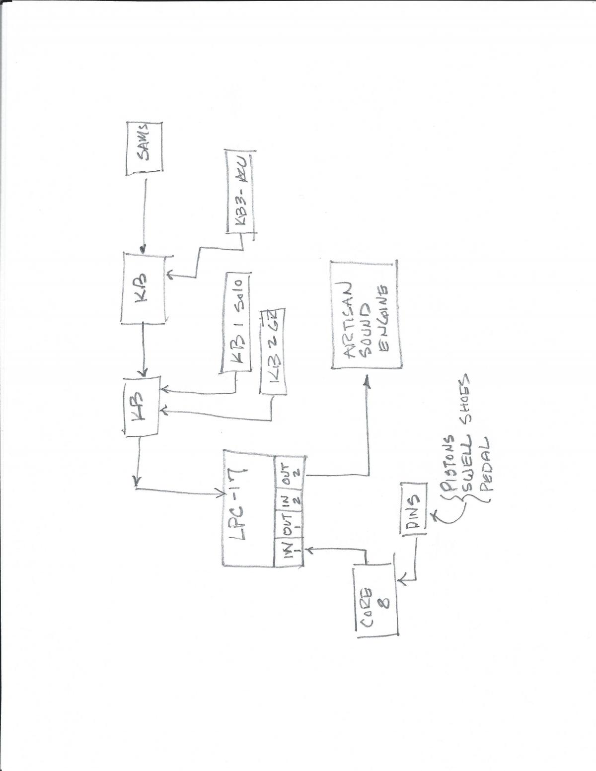
Hardware: A 3 manual midified organ console , with (64) SAMS, 42 pistons, (2) swell shoes, (1) cresendo pedal.
Relay components:
One (1) LPC17
One (1) Core8 w/ 3 DINS (DIN inputs are pedal (32 notes, channel 4); pistons, contacts on 18 SAMS, Contacts on Rotary Swell Shoe drum controller all on channel 15) .
Two (2) KB modules - encoding three keyboards(61 keys each, channels 1,2,3) , and contacts on 64 SAMS on channel 5.
Config .MIO defines output on matrices as midi OUT2. Core8 messages route IN1 to OUT2.
Modi Router OUT2 feeds Artisan sound Engine.
There are no other connections to the LPC, no PC.
Sound Source is an Artisan Soundengine.
The organ operates normaly. All console functions are operational
Artisan soundengine displays all midimessages as recieved from the midi OUT2 port on the LPC17.
PROBLEM:
Keys pressed and stops set (channels 1,2,3,5) do not show up on soundengine display when playing back a file recorded on the recorder and there is no sound from the soundengine..
Expected message would be of the format C1N60. Yes - stops are set after recorder is engaged.
help!
Johnc
-
Pete,
I posted a note to TK in the midio128 ver3 thread referring to this thread regarding the recorder/player. i never know where to put my posts.
Hopefully TK will find that post, or this one and respond. He seems to keep up with whats going on.
In the past, you gave me some help with issues regarding DOUTs especially when UL2803 drivers were emplanted on the DOUT pcbs. Also grounding and power supply issues with the LPC and DOUTS.
You may have notices that the block diagram i posted earlier on this thread was devoid of the Driver chain of DOUTS and all discussions of SAMS. Following those posts, I continued to have problems with the douts with drivers on the pcbs and finally decided that the overall design of the organ relay was too frought with issues to continue, so I changed over to a Peterson combo action system which came to me without charge. The overall system, excluding the peterson Combo, however, remained the same, inparticular the LPC17 and all encoding KB modules, etc. In addition, the lack of a reliable analog capability with the LPC forced me to find other means to support the swell shoes and cresendo pedal.
I still feel strongly that a complete, reliable pipe organ relay (winded pipe system) can be built out of midibox hardware, but not without someone with programming skills, taking the time to modify midio128 to include a comb action. With that in place, there would be no need for a computer, jorgan, miditzer are any other device. For VTO, A computer is still needed as a soundsource, or a separate sound engine device similar to the Artisan soundengine.
At 75, my interest in all this stuff continues, but my resolve to continue fighting problems, etc. is waining!
You are always willing to jump in and offer assistance, and I greatly appreciate that.
Have a great Thanksgiving!
Johnc
-
TK,
Please take a look at posts (John's organ midification)concerning recorder/player issue involving keyboard inputs from 8x8 matrices.
Kpete has been assisting and suspects a problem with the recorder.
Thanks,
johnc
PS: should this post be in this thread, or someplace else?
-
Pete,
1. I sat on the bench, set the stops I want to use, played a bit. all good.
2. using the control surface, I started the recording, noted the time incrementing on the right end of the LCD, The "recording" was blinking.
3. Went back to the bench and the keyboards are dead, nothing, no sound at all.
I have the dig I/O with both play and record checked, and the same for midi1 and midi 2.
What does the ****ALL DOUTs DEACTIVATED**** mean. If the DOUT pins are deactivated, the matricies won't encode. How is this changed?
Should I wait until after the LPC is in record mode to set the stops, then play?
Confused and frustrated!!
Johnc
-
Pete,
Thanks for the patience with my questions.
My understanding of how the player works is improving, but not the why!
At this point, I would have to ask - How do I get the player to record the keyboard and SAM sensor data as well as the stuff coming from the core 8 thru the router at the same time?
I am suspecting that what enters a router midi in port and exits a router midi out port, is basically not seen by the LPC. Therefore, if i did away with the core8, and tied the DINs to the J2 on the last KB pcb, then the player would record everything. Yes? I would need at least the pedal data.
You stated "These all can be changed and saved without affecting your router settings", concerning the midi1 and midi2. How?
What is the difference between the DI/O data and midi1 or midi2 data? I am not understanding the why and wherefore of midi1 and midi2!
Thanks,
johnc
-
Hi Pete,
Thanks for the input.
Does selecting midi2 mean that the recorder will record the midi out2 port on the router,and play the midi in2 port on the router.
I went through the process as you described but still got nothing.
Notice on the diagram I attached that all midi messages from the console are routed through midi out2 to the soundengine. Midi in2 is not used. All midi messages from the core 8 (pedal,pistons, couplers, swell shoes) is routed to midi in2 and out midi out2.
Johnc
-
Kpete,
you have some posts dealing with the recorder/player on midio128 V3, and seem to be up on the player.
Is there some special setup as regards the router in the LPC-17 and midio128 v3/
As you may recall, i am usng 2 KB modules with 4, 8x8 matices for 3 KB's, & SAM contacts, and an additional line with one core9 and DINS for pedal and pistons. The organ operates without a computer attached on the front end, no jOrgan, miditzer, etc. using the router, all midi out messages go out on "out2" to an artisan soundengine.
each of the matrices specify midiout on out2; the midiout on the core 8 connects to "in1" on the LPC.
I have tried the midi rec/ player which appears to record, but there is no playback.
Is there a setup to select the source router port for recording and the destination router port for playback.
Lastly, will the recorder capture everything, stop changes, pistons etc.?
Organ is fully functional. see attached diagram
Thanks,
Johnc
-
Mumblecake,
I didn't mention, but i am using two KB modules with the LPC17 for 3 KB's and SAM sense contacts. I started out with a 16x16 matrix, but the simplicity od the KB's in conjunction with the LPC17 changed my mind. I also built the SAMS sense matrix by putting the diodes directly on the SAM, and building the matrix with jumpers, resolving to 2 8/c ribbon cable to the KB module. Probably a big antenna, right. Live and learn! while having the spontaneous action, i did a wiring consolidation, separating the wiring from the douts to the SAMS from the wiring for the sense matrix to the KB modles. That helped a good bit. considering the spread of wires connecting to the DINS or the DIN side of the KB modules, the only way to do a better job of isolation would be to use shielded wiring.
When I started out with midification (2004), All i could see was the potential applications, with no specifics or input to tell me that in the end, it may be going a bit too far.
I still feel that if i worked with it long enough, I could resolve the issues. At 75 years old, it is becoming difficult to see the small stuff, and to keep the details straight in my aging, slow memory.
Johnc
-
Is the NG a functional replacement for midio128 ver.3?
Pedalboard midification using a keyboard
in MIDIfication
Posted
Ok, I follow your wanting to midify the pedalboard, but "making the pedals hit the white keys of an M-Audio keyboard..." eludes me, especially the "hit"
Do you want to play the m-audio board system from the organ pedalboard, or play the pedalboard notes on the organ from the M-audio keyboard?
Midifying the pedalboard to add contacts which can be wired to an encoder is easy. modifying the m-audo keyboard to insert a contact, or to modify the internal circuitry is something else entirely.
Can you clarify exactly what your intentions are.
In the meantime, you may want to search the midibox forum for "midifying a pedalboard"
johnc