

John_W._Couvillon
-
Posts
350 -
Joined
-
Last visited
Content Type
Profiles
Forums
Blogs
Gallery
Posts posted by John_W._Couvillon
-
-
Duggle, Pete,
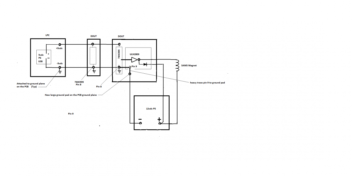
Take a look at the attached sketch.
As long as the only point of connection between the two loops is the new ground lug that i show on the DOUT pcb, the high current loop involving the 12vdc PS, magnet coil and driver on the ULN and the 5vdc loop though the I/o cabling should remain separate. When the ULN conducts the voltage from pin 9 (gnd) to any of the output pins drops to less then 1 volt and the current from pin 9 to any one of the output pin goes up to 200 - 300ma. Pin 9 on the ULN must be connected to pin 8 on the 595 which is at ground plane potential, however the current flow will be normal.
Adding a high current jumper from pin 9 on the ULN to the new grond lug, ot a beefier trace will do the job. and minimize voltage drop in the loop, so that the voltage across the magnet is as high as possible.
Johnc

-
Duggle.
The current path as you describe it is accurate!
Looking at the two main devices, the 8bit core and LPC -- The 8bit core uses a wall wart, but the core has its own rectifier and regulator, the -5v side being grounded to the core ground plane. The LPC accepts 5vdc fromt he USB connectiion, but also has its own power supply, with grounded negative. Each train of I/O is powered through the 5/c i/o cable interconnecting the DINS snd DOUTs.
if there were no ULN2803 drivers there would be no need for additional 12vdc PSU, or additional common ground point.
Adding the ULN Drivers on the DOUT pcbs and creates the need for an additional 12vdc PSU, which by design, must have a common connection point which turns out to be the backplane of the DOUT pcb. IMHO, The back plane of the DOUT PCB is the common with regard to the two supplies. Current will flow as you described in the 12vdc loop, and current will flow through the 5vdc loop, however the common backplane of the DOUT pcb is the only tie. So i agree, there is no ground loop. The ground plane of the core 8 and LPC should remain floating.
Johnc
-
Pete,
you are correct on the J1/j2 issue of not continuing some of the DIN wiring past j2. Since i did not intend any DINS beyond that point, and since all bu the SI and SO pins on j2 are duplicated for Dout and DIN I used only a 5 pin connector.
Also involved in this project are quite a few old DIN4X and DOUT4X boards which have been around since i built my first Virtual instrument with revision 0 of SMASHTV pcbs. The DOUT4X I am having the problem with is a modified DOUT which pre-dates SMASH's revision of the board to accept the ULN2803, just guessing i would say 2003 or so. So this board has seen a better day. This morning I decided to give up on it and order a new Dout4X and start fresh, I have already spent many multiples of $15.00 in time. In the mean time I'll work on the soundengine part and get some sound going.
Thanks for the input, comments, etc. its nice to have someone to discuss this stuff with, especially the hardware side.
johnc
p.s. I touch soldered all of the 595 ics socket pins but nothing changed, except now touching anyone of the 4 makes the SAMS on the DOUT pcb flip up and down. I agree, somehow the clock pulses are not getting through. to the PCB. With a new DOUT4X that works, either the problem will go away, or it will move upstream. I do know that the DOUT4X that connnects to the last matrix bd works, so that narrows the search range.
-
Duggle,
That sounds good, but would require a total new PCB design with new PCB's for 64 sams, not to mention the cost of the nchannel mosfets, even in a quantity of 100. There is one commercial line of driver boards using the 74HC595 which drives simple 2n222 single transistor drivers. thats 128 transistors, but they are cheap.
for the time being, SMASH TV's pcbs are the best value going.
My current problem (different thread) deals with grounding issues when using a 12vdc PS for the SAMS magnets. The 28ga ribbon cable ground conductor that loops through the DOUT4X pcbs was never intended to pass high amps produced by the SAMS aps, nor was the ground trace on the PCB's. In an attempt to resolve the issue, KPete recommended attaching a high capacity (#18ga) ground lead to the ground plane on all Dout4X pcbs and terminating them at one poiint on the -12vdc supply. Assuming the new grounding path is sufficiently low impedence to keep the current through the ribbon cable in limits. In addition, The LPC uses USB power, and the 8bit core uses a wall wart. The wall wart -5vdc can be connected to the -12vdc common point, but not the USB power. Again the recommended fix is to solder a good ground on the the grounded back plane of the LPC and affix it to the -12vdc common point. That creates ground loops big time.
To bad that technology doesn't provide an optical connection inbetween the 74HC595's and the ULN2803, whereby the magnet power could be isolated from all other supplies. probably could be done, with some optical isolation. All you need is a way to switch 5vdc on the input to the ULN to turn it on or off. Any thoughts. Take a look at "midification" midio128 ver. 3. there is a block diagram of my organ system. Clearly, IMHO, there is a need for a high current solution when dealing with DOUTs and low imped. magnets such as SAMS. Driving organ pipe electromechanical pallet valves works just fine, much lower duty cycle, however, grounding and high current return path to the negative PS term is still a problem..
Please take a look at the datasheet for the MIC5841/5842, http:/www.micrel.com. Note in the General Description, Page.1, "The drivers can be operated with a split supply where the negative supply is down to -20V". The split supply is what caught my eye, in view of the grounding situation described above. would this design aid in keeping the 12vdc power loop isolated from the 5VDC logic supply? using the MIC5841 would allow more space on the pcb for larger ground traces, and output traces from the drivers without increasing the overall PCB size . your comments please.
Johnc
-
Pete,
The ic's involved with the proximity issue are on the DOUT4X that is down stream from the two matrix boards. you say floating input pins, but the only input pins feeding into the LPC are in the 4 matricies, (three keyboards and SAMS reed contacts) inputs. could it be an open circuit in one of the Matricies. I haven't noticed any notes not playing, or pistons not working.
Would a lose connection or bad solder joint on an input pin on the 595 shift register cause what we are seeing?
i'll touch my soldering iron to all the input pins on the 595's tomorrow.
All the other inputs of which there are almost 64 (pedal keyboard and pistons)are on the DIN train that is connected to the core 8.
Thanks,
Johnc
-
pete,
As of today, all SAMS work with the jOrgan either by picking with the mouse on the desktop, or by using a piston, with exception of the last addition to the DOUT train that is connected to the LPC. specifically it drives all but 3 of the SAMS on the pedal. This particular DOUT4X is the one where i am only useing 16 douts, Two uln2803s are not installed. Without the last DOUT4x plugged in to the 5/c LPC chain, everything works. When I plug in the last DOUT4X, initially the SAMS tied to it are not responding to the screen picks or pistons. now the strange part, if I put my finger in close proximity to the back of the first DOUT stage,74hc595 and Uln2803, the sams connected begin to randomly jump back and forth from on to off. Removing the finger, it stops.
So I:
1. Removed the 5/c jumper from the upstream DOUT4x and verified continuity through the jumber - no problem.
2. I inspected the solder connections on the back side, in particular the trace connecting to the middle SO pin starting on J1 through the first DOUT then the second, third and forth.
3. I replaced the 595 and the uln chips.
Thie above did nothing.
The other midi out routes the note on /note off Stop messages from jorgan to the Soundengine, as well as key press info from the keyboards. Actually, it is not installed, although shown on the diagram. I haven't got it yhe SE producing sound yet, only running jOrgan.
The router on the LPC is configured to route only select channels to the SE.
I think that everything is fine, with exception of the last DOUT4X. If I could figure out what is wrong with it, all would be well.
I appreciate being able to bounce my problems off of you!
I do have a lot of time and effort in this project and thias little glitch is holding up the show!
PS: The last DOUT4X has a dedicated lead from the ground plane back to the common -12vdc ground point.
johnc
So as it stands, with the last DOUT4x on the LPC chain disconnected, everything works.
I am puzzled by the proximity issue ( not touching any pins)?
Any comments.
As for the SAMS. they are Syndyne with positive coils, and one reed switch. They worked fine on initial bench checkout and appear to work quite satisfactorly. They were in service previously driving pipe magnets on my now defunct 5 rank pipe organ. The way the SAMS extension works in jOrgan is that upon receipt of a note on message, it energizes the on coil then intercepts the reed switch closure (positive mech. feedback) which means that the armature moved to the on position and is magnetically (permanent mag on the SAM) held, once the reed switch closes, jorgan terminates the pulse to the on coil. There is also a 500ms time out which terminates the pulse in case the armature sticks, etc. on receipt of a off message, it performs the same way bu works with the off magnet. Complicated, but it works.
-
Duggle,
Ok, i see your point.
i am probably miss interpreting the notes on the max ratings table (motorola Datasheet) it says
MAXImUM RATING (Ta=25deg, C, and rating apply to any on device in the package, unless otherwise noted)
Below the table it says: Do not exceed maximum current limit per driver.
If you are running SAMS with 30 -40 ohm coils, thats 300 - 400ma each, connecting 4 sams to one 2803 means there is a possibility that a gen cancel will cause 4 off coils to be energized at the same time, for .5 sec. if i understand you accurately, it is allowable to have all 8 outputs on at 312 ma with out exceeding the max. temp rise over ambient. since only 4 of the 8 will fire, then i should have no problem.
Am I reading you correctly.
johnc
-
Duggle,
The 5841 appears to contain the equivalent of both the 74hc595 and the uln2803. From an application point of view, using the 5841 the DOUT4X would need only 4 ic's on the pcb rather then 8. Actually the 5841 is used on a popular brand of SAMS driver.
Look closely at the datasheet, only one of the 8 outputs can carry the 500ma at a time. The ic cannot carry all 8 outputs at capacity.
-
Pete,
As for the pin10 spike, it could be a problem as i assumed wrongly that there was minimum current flow, and the connectiion from the pin to 12vdc is no more then 26-28ga.
As for the SAMS, i am using the sAMS extension in jorgan which utilizes the reed switch on the SAM in the time delay process where by the pulse to the magnet lasts for only 500 ms (adjustable). I have not noticed any problem therein.
Srr the attached block diagram
-
Is it possible to substitute a MIC5841 8bit Serial-input latched Driver for the 74HC696/ULN2803 pair in the typical combo for driving magnets, excluding the current DOUT pcb design.. The 5841 will allow 4 outputs on (200ma @12vdc) at 70 deg. c ambient for an 86% duty cycle, , or 100% duty cycle for 3 outputs on at 70 deg. c ambient. In an application using one 8 bit driver package to serve 4 SAMS ( 4 on magnets and 4 off magnets) where max condition would be 4 outputs at capacity per 8 bit driver. As i understand the ULN2803 spec, only one of the 8 outputs can be at capacity at the same time. Seems a better optiion.
Johnc
-
Pete, TK,
Please feel free to move this thread to Design concepts or someother topic.
I will install the revised grounding including the LPC and the core 8, test it then report back.
if you have more thoughts in the meantime, please post them. i am in the late stages of construction on the console, and i hate to remove working systems, with the allways preasent possibility of inserting new issues.
In general though, IMHO, I have implemented the DIN, DOUT. and matrix IO cards within the posted guidelines. How should I have done it to avoid this problem, including the grounding issue?
Thanks,
johnc
-
Pete,
You are just full of good news! but tell me more, Please
you said:
"Something else that worries me is that you have a DIO-Matrix board between the LPC17 and your Dout chain. It so happens that just before reading the Din chain, the shift registers are loaded with the RC strobe signal. This same signal also strobes the Dout shift registers into the output holding registers. So when the outputs are changed to the SAM's, the input shift registers are being loaded at the same time. Could there be noise getting into the Din chain of the matrix board?"
Ok - So what is the solutiion? The mio pcb uses Din and Dout, and the SAMS Dout boards start with D5, D1 thru D4 being used by the mio. Would reversing the do order do any good. Can I connect the DOUTs for the SAMS to a different connector on the LPC?
Wow, 2 amperes on pin 10 of the 2803. Didn't know that either, nor have i ever read any warning. i suspect the connections from the pin 10 back to the +12v should be #18awg also.
Would have helped to know all thie good stuff before screwing all the pcbs to the backplane.
Thanks for the input, and please pass anything else along.
johnc
-
Pete,
Thanks for the explanations.
Finding a place on the LPC to connect a ground pad is difficult - any suggestions? Bare in mind that all the pcb's are firmly attached to a back plane.
An underlying problem that may be connected is that when the J1/j2 jumper is plugged in to the last DOUT4x, multiple SAMS begin turning on and off randomly.
Johnc
-
Pete,
Currently, the LPC is USB powered from the Artisan sound engine computer which is running jorgan. The SE computer boots up in linux ubuntu which takes a 10-15 seconds after powwer is applied, After Ubuntu is loaded jorgan auto boots up in to the disposition. since the Soundengine, 12vdc supply,, 5vdc supply for the core 8 all come on at the same time as the computer, I would have to say that the 12vdc is applied long before the shift register chain is innitialized. this is definitely something that is new to me. since I have a core 8 with DOUTS driving SAMS also i suspect the same problem exists.
Question; So what happens if the 12vdc comes on before the DOUT shift register is initialized. I suspect that i could switch the 12vdc and 5vdc power separately, or time delay with a relay which would be preferred, on switch turns everything on!
The LPC has only 6 DOUTs connected, which can be in excess of one ampere. The 5 conductor ribbon diasy chain from the LPC on down through the MIO pcbs and DOUT cards is in place. I understand about the 18awg ground from each card, and i assume you mean from the ground plane of the PCB to the common ground point, leaving the ribbon cable interconnect in place?
With that done, is it necessary to put another ground on the LPC?
To be sure that i have this right, i will post a block diagram of how it exists now, i how i understand your suggestions.
Question: There are 2 dout4x pcbs connected to the LPC as described above, but only two ULN2803 are installed on the last DOUT4x(last 2 sockets are empty), however there are 4, 74HC595 installed. i don't need the last two ULNs. is not having pull down/up resistors on the last two 595's a problem?
Thanks for the help,
johnc
-
Thorsten,
Questiion: The order of MIO and DOUT PCBs cards and jumpers is LPC to matrix pcbs first in line then the 3 DOUT4X PCBs, Using ribbon cable and connectors makes the Vs terminals inaccessible. Can I just drill a hole in the ground plane on the DOUTS, install a pin connector with soldered ground lead?
Question: with the core 8 Dout Chain, Is only one connectiion from Vs on J1 of the first DOUT to the system ground sufficient. The existing interconnecting jumpers are 24Ga copper, 0.5 inch long, soldered, J2 to J1 inbetween each card. Would it harm to install a larger ga ground from each Vs jumper between PCBs to the common system ground? Each Uln2803 serves 4 Sams, two 40 ohm magnets each on adjacent DOUT pins, but the on and off coils are not energized at the same time, so max load per PCB is 4.8 amps. On the core 8 chain with 4 DOUT4X PCBs at 4.8 amps thats 19.2 amps. Realistically, one magnet on every SAM either going on or off is not probable, so applying a diversity factor of 70%, there could be a 13 amp load which could explain why some of the SAMS are not moving as fast as others. In any event voltage drop in the 24-26ga wire sizes whether ribbon or solid conductor becomes an issue. Granted 90 or higher ohm magnets would be good, but we use what we have.
perhaps, Smash would consider higher capacity ground traces on the DOUT4X Pcbs with a higher capacity ground lug apart from J1 and J2.
Question: Would it be better to use one multi-voltage PS providing DC for the LPC at 3 or 5vdc regulatrd, 5vdc, regulated for Core 8 and each I/O PCB and a stiff 12vdc at 20-30 amps for SAMS, eliminating the Vs cable link in the card to card jumpers, and powering every card through a fuse directly from the PS, or possibly a fuseholder on the PCB.
Question: Is it possible to insert a low power LED on both DIN4X and DOUT4X as well as MIO PCBS to monitor either shift register action, or clock pulses to be able to flush out SR chip issues.
The LPC core is super. Thanks Thorsten - I can see several great applications utilizing the horsepower of the unit with regard to pipe organs and virtual organs. Unfortunately, i am a bit too old to start a new carrer in programming. If anyone out there is interested in a discussiion on the subject, please send me a personal email.
At this point, IMHO, there is only one organ function that a midibox based organ relay can't do, and thats provide the software to implement a combination action system. The hardware can do it, and MIOS and midio128 Ver3. already provides for the I/O functions, but not the capture action, storage and combination retrieval. Why have to use a PC or a Mac to run jOrgan, miditzer, hauptwerk when the LPC hac the smarts to do it all?
Thanks,
Johnc
-
Thorsten, Forum,
Currently, I have active, an LPC-17 running 4 (8x8) matricies, 3 scaning keyboards, one scanning pistons, and 10 additional dout stages in 3 DOUT4x pcbs. The 10 stages of DOUT drive various SAMS on the console which operate at 12vdc from a stand alone 12 volt powersupply. The LPC is USB powered from a PC running jorgan. in additiion, there is an 8bit core, fully loaded, 4 DIN4X and 4 DOUT4x connected to the LPC router, and powered by a 9vdc wall wart. I am running midio128 Ver. 3
my concern revolves around the power supply interconnection on the ground side.
All of the DOUTS in the LPC stream have UULN2803 drivers using the common pcb ground from card to card back to the LPC. which has no ground point for tie in to the 12vdc powersupply tor the SAMS. Each SAM coil can draw just under 0.5 amps, so it doesn't take too many SAMS to be set or cleared to generate a sizable amp load through the ground path back to the LPC and its USB power source.
For the 8bit core, the same thing is true, however, the negative leg of the 9vdc wall wart is tied to the 12vdc negative of the 12 vdc Sams power supply.
Question #1 - is the high amp draw of the SAMS thru the pcb grounds to the LPC a problem? How much load is safe?
Question #2 - How do I develop one common ground point for the 3 power sources, especially the LPC?
Thanks,
johnc
-
Kpete,
Great stuff!
I knew that there must be something out there!
Thanks!
Johnc
-
Pete, Technobreath;
yes you are correct, however I have added several DOUTs to the two matix pcbs that are feed by my LPC17. the ULN2803's feed the magnets on 32 SAMS and overheat for no apparent , obvious ,reason. Now i have a pile of ULN's and don't know if they are good or bad. I hesitate to plug a questionable chip into a working circuit. Yes the ULN's are cheap, but just the same.
Thanks
Johnc
-
Forum,
I'm having circuit problems in the new matrix pcb. Replacing the chips after each test is getting expensive.
Does anyone know of a test rig, DIY or commercial that could be used to checkon the viability of a ULN2803.
thanks.
-
CSC,
So you have the 220 ohm resistors in parallel with the diodes?
Do you have a schematic of your circuitry?
Thanks,
johnc
-
Thanks for the input. The DIN is an older one and I don't think that it has bypas caps. I'll check it out.
-
Midio128, ver. 3, LPC17, using three matrices for keyboard encoding.
In connecting the DOUT through the keyboard contact and diode to the DIN, the series 220ohm resistor usually on the DOUT has been eliminated. with this arrangement, I seem to be losing DIN 74HC165 chips. Pressing a key brings the correct note, plus others. Changing the DIN chips corrects the problem. Am I just paranoid, or is there an inherent problem with the circuit arrangement?
Johnc
-
Tim,
no Sweat. you do a great job.
I particularly like the LPC board. it is a super board, and works great for me.
I am involved with several pipe organ situations involving electronic components by Syndyne, Artisan and others, and don't find any of them superior to the midibox modules. The LPC has the capability of toping any of them with a bit more custom programming especially in the Combination action area. With that code added to the midio128 ver 3., you could compete with any of the commercial products.
Keep up the good work.
Johnc
-
hi Tim,
So you are ahead of the game. Thats great! no offense intended. Please forgive if i offended you.
So the box connectors can fit with the off the shelf pcb's, with as you say some shaving. We did that with fitting the ULN2803 chips on the DOUT card as you remember. I am still using those modified DOUT4X pcbs. not the most attractive, but they work. I well understand your point about costs, etc., but I also remember the revisied pcbs to add the ULN chips to the DOUT cards. The adjustment doesn't technically change the card, but lowers the probability that the connectors go on backwards. Not all constructors of your kits have technical backgrounds. most follow the assembly pictures and the words. I'm not offering criticism, just a suggestion. Most assuredly, we don't want to increase the costs of the kits.
Johnc
DOUT chip Substitution
in Design Concepts
Posted
Duggle,
Back to our original discussiion of the position of ULN outputs and initialization of the shift registers on startup, If stops are on when the organ is turned on, they are immediately cancelled when jOrgan come on. Boot sequence is midibox cores, ubuntu, the soundengine, then jOrgan, and lastly the disposition. jOrgan sends out a note off message to all off magnets, whether they are on or not.
My 12 volt power supply is a converted computer PS which is only rated for 10 amperes at 12vdc, and if it is on during boot up, it immediately trips out when the jOrgan disposition boots. The off magnets on 32 SAMS is sufficient to trip it out. I need a higher capacity PS. simply unplugging it for 10 seconds allow it to reset.
Johnc