
Marxon
-
Posts
474 -
Joined
-
Last visited
-
Days Won
4
Content Type
Profiles
Forums
Blogs
Gallery
Posts posted by Marxon
-
-
According to mapmidi.ngc from the SVN
# Note: it's possible to assign the same ID to multiple senders# advantage: only a single receiver has to be defined, which then forwards to multiple sender located in different banks
So it should work.
EDIT:
...located in different banks.May this is my problem.
-
The right most digit
-
Hi ilmenator,
I checked everything multiple times. Replaced the 595s, digits, cables and boards.
For me the 2nd digit seems to react like "standard" led matrix pattern instead the LcDigit pattern.
And if the pinning is messed up should the first digit not be affected too because the cathodes have a parallel wiring?
Best regards
Marxon
-
Hi Midiboxers,
i noticed some very strange behavoir when using this code.
DOUT_MATRIX n=1      rows=8   inverted_row=1 inverted_sel=1 mirrored_row=0    sr_dout_sel1=1 sr_dout_r1=5
# -- -- -- xx
EVENT_RECEIVER         id=4  fwd_id=SENDER:4          range=0:127    type=CC chn=1 cc=104
EVENT_SENDER           id=4  fwd_id=LED_MATRIX:2
EVENT_SENDER           id=4  fwd_id=LED_MATRIX:1
EVENT_LED_MATRIX     id=2  led_matrix_pattern=LcDigit
EVENT_LED_MATRIX     id=1  led_matrix_pattern=LcDigit
This video shows what happens when sending CC104
But should the digits not look the same?
Best regrads
Marxon
-
Hi Thorsten,
to describe the issue without
ich bemühe mich keine Romane zu schreiben und die Beiträge auf das wesentliche meines Anliegens zu reduzieren.
Klappt leider nicht immer :smile:
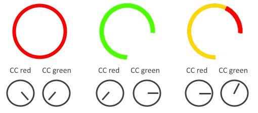
I made a ring out of 32 duo colour leds driven by three SRs connected like a 8x8 matrix.
Row 1-4 form tbe four quarters of the ring (a second ring with 32 leds is connected to row 5-8...)
Now i want to control the red color with a CC and green with another CC like this picture:
Because i did not find a better solution i simply mix green and red with this code:# EVENTs [connector RINGS]------------------------------------------------------- # --------------------------------------------------------------------------------- DOUT_MATRIX n=1 rows=8 inverted_row=1 inverted_sel=1 mirrored_row=0 sr_dout_sel1=2 sr_dout_r1=1 sr_dout_g1=3 # Ring 1 Red EVENT_LED_MATRIX id=625 type=CC chn=1 cc=111 range=0:32 led_matrix_pattern=5 colour=0 EVENT_LED_MATRIX id=626 type=CC chn=1 cc=111 range=32:64 led_matrix_pattern=5 colour=0 EVENT_LED_MATRIX id=627 type=CC chn=1 cc=111 range=64:96 led_matrix_pattern=5 colour=0 EVENT_LED_MATRIX id=628 type=CC chn=1 cc=111 range=96:127 led_matrix_pattern=5 colour=0 # Ring 1 Green EVENT_LED_MATRIX id=629 hw_id=625 type=CC chn=1 cc=112 range=0:32 led_matrix_pattern=5 colour=1 EVENT_LED_MATRIX id=630 hw_id=626 type=CC chn=1 cc=112 range=32:64 led_matrix_pattern=5 colour=1 EVENT_LED_MATRIX id=631 hw_id=627 type=CC chn=1 cc=112 range=64:96 led_matrix_pattern=5 colour=1 EVENT_LED_MATRIX id=632 hw_id=628 type=CC chn=1 cc=112 range=96:127 led_matrix_pattern=5 colour=1 # Ring 2 Red EVENT_LED_MATRIX id=633 type=CC chn=1 cc=113 range=0:32 led_matrix_pattern=5 colour=0 EVENT_LED_MATRIX id=634 type=CC chn=1 cc=113 range=32:64 led_matrix_pattern=5 colour=0 EVENT_LED_MATRIX id=635 type=CC chn=1 cc=113 range=64:96 led_matrix_pattern=5 colour=0 EVENT_LED_MATRIX id=636 type=CC chn=1 cc=113 range=96:127 led_matrix_pattern=5 colour=0 # Ring 2 Green EVENT_LED_MATRIX id=637 hw_id=633 type=CC chn=1 cc=114 range=0:32 led_matrix_pattern=5 colour=1 EVENT_LED_MATRIX id=638 hw_id=634 type=CC chn=1 cc=114 range=32:64 led_matrix_pattern=5 colour=1 EVENT_LED_MATRIX id=639 hw_id=635 type=CC chn=1 cc=114 range=64:96 led_matrix_pattern=5 colour=1 EVENT_LED_MATRIX id=640 hw_id=636 type=CC chn=1 cc=114 range=96:127 led_matrix_pattern=5 colour=1 # LED Patterns LED_MATRIX_PATTERN n=5 pos=0 pattern=0000000000000000 LED_MATRIX_PATTERN n=5 pos=1 pattern=1000000000000000 LED_MATRIX_PATTERN n=5 pos=2 pattern=1000000000000000 LED_MATRIX_PATTERN n=5 pos=3 pattern=1100000000000000 LED_MATRIX_PATTERN n=5 pos=4 pattern=1100000000000000 LED_MATRIX_PATTERN n=5 pos=5 pattern=1110000000000000 LED_MATRIX_PATTERN n=5 pos=6 pattern=1110000000000000 LED_MATRIX_PATTERN n=5 pos=7 pattern=1111000000000000 LED_MATRIX_PATTERN n=5 pos=M pattern=1111000000000000 LED_MATRIX_PATTERN n=5 pos=8 pattern=1111100000000000 LED_MATRIX_PATTERN n=5 pos=9 pattern=1111100000000000 LED_MATRIX_PATTERN n=5 pos=10 pattern=1111110000000000 LED_MATRIX_PATTERN n=5 pos=11 pattern=1111110000000000 LED_MATRIX_PATTERN n=5 pos=12 pattern=1111111000000000 LED_MATRIX_PATTERN n=5 pos=13 pattern=1111111000000000 LED_MATRIX_PATTERN n=5 pos=14 pattern=1111111100000000 LED_MATRIX_PATTERN n=5 pos=15 pattern=1111111100000000
Thats what i meant when I said the resulting orange color is made of two "single color" events.
Now the question:
Does it make a electrical difference to mix a led color this way instead of using the rgb=xx:xx:xx parameter?
Best regards
Marxon
-
Hi all!
Because there are various ways to set the colour of a rgb led,i wonder does it make a difference if a colour inside a rgb led matrix
is made of multiple single colour events respectively a single rgb event?
I guess yes.AFAIK the rgb event uses pwm to mix red green and blue.
So creating orange by simply turn on red and green is not a good way.
Is this correct?
Best regards
Marxon
-
Hi Midiboxers,
there seems to be a bug with the "colour" flag because
MIOS Studio reports this error if colour=0
[72901.670] [MBNG_FILE_C:35] ERROR: invalid flag in EVENT_LED_MATRIX ... colour=0 (expect 0..2)
The error is caused by this event:
EVENT_LED_MATRIX id=1 hw_id=1 type=CC chn=1 cc=111 led_matrix_pattern=1 colour=0 no_dump=1
If colour=1 or colour=2 no error occours.
Maybe someone can test/confirm this behavoir?
Best regards
Marxon
-
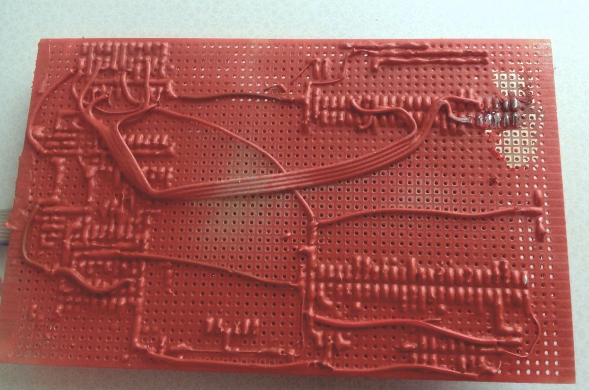
Hi MidiBox Community!
Because I have built all my Midibox projects out of breadboards, it happens quite easily that small solder, wire or other particles short tracks. So i was looking for a way to seal their backside somehow.
Usually baords coated with a green solder mask but my breadboards have a very uneven surface
so this was not suitable.
Some time ago i found something interesting: rubber spray http://www.plastidip.com/home_solutions/Plasti_Dip
It is mainly used for car rims but the properties sounded quite promising
- Latex-based synthetic rubber formula is flexible and stretchy
- Air dries in as few as 30 minutes
- Provides a comfortable, controlled grip that resists moisture, acids, abrasion,
corrosion, skidding and slipping
- Will not crack or become brittle in extreme weather conditions
- Resists chemicals, impact and abrasion
- Prevents electrical shock and vibration, resists heat and deadens sound
Unfortunately, there have been no reviews whether and how well the spray is suitable for circuit boards.
Nevertheless, I gave it a try´ and ordered 2x400ml for 13€
First I cleaned a board with a printed circuit cleaner (Kontak LR/Kontakt PCC) and isopropyl alcohol,
then I sprayed several layers and let them dry for 15 minutes each.
After five layers the board surface looked well covered with rubber.
The mechanical resistance it is really good.
The board is well protected against screwdrivers. connector pins and other sharp parts...
Since it may possibly be necessary to solder on a circuit board again,
the rubber is removeable.
On a flat, smooth surfaces, it can easily, peeled off in one piece with finger,
on breadboards it is a litlle bit more fiddly.
To remove it from solder points, it is better to scratch with a sharp tool.
All together my expectations were met and i am quite happy with this rubber spray.
Best regards
Marxon
-
Hi all!
What's the status of the ssd1298 driver for MIOS?
Is a release planned?
Best regards
Marxon
-
Hi Roel,
this sounds really strange...
I would stuff the DIN board with only one 74HC615 first to test if it works correctly.
Next, add the second 74HC165 and test again...
Marxon
-
Nobody?
-
The dealer sent me immediately the correct board and i could retain the other one.
If anyone is interested in the STM32F429I-DISCO board
i would trade it against a PIC18F4685 with bootloader.Look
Best regards
Marxon
-
Hi all,
i have received a wrong STM32F429I-DISCO board
If someone is interested i would like to trade the board against
a PIC18F4685 with bootloader.
Best regards
Marxon
-
Sorry Shuriken,
you are right. 5€
Because i paid more then the Mouser price.
OK topic finally closed :)
-
-
Hi TK!
It's the board that we discussed here:-> currently not supported, and will lead to incompatibilities
-> sell it
Sorry i should have used the forum search before. :blush:
Ok i will sell the board.
The seller did sell you the wrong board though. Maybe you can get your money back. The description clearly says STM32F407.That´s why i was so surprised.
But it looks like the delivered Version is a lot more expensive then the correct STM32F4 board
so i get a second board nearly for free :cool: :D :cool:
Best regards
Marxon
-
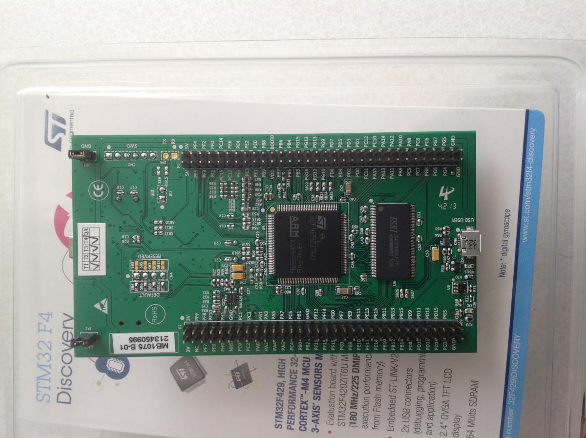
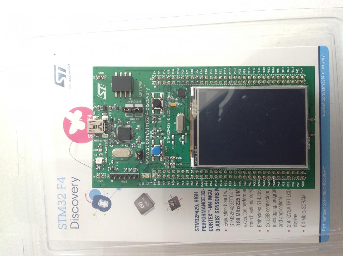
Hi all,
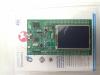
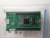
i was a little bit surprised when my new STM32F4 board arrived
because i ordered this one:
But i received this Version

Now the big question:
Is it compatible?
If needed it would be no problem to change the core board wiring.
Best regards
Marxon
-
Hi Thorsten
Unfortunately this does not help.
EDIT:
I forgot to do a restart after i had changed the system variables.
Now it works!
Thanks a lot. :thumbsup:
Marxon -
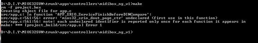
Hi!
When i try to compile the original Midibox NG app from the SVN then
i get the following error:
First I suspected there is something wrong with my toolchain or system variables but
other MIOS32 apps compile without problems..
Maybe there is a bug in the actual SVN source?
Does anyone else get the same error message?
Best regards
Marxon
-
Hi John
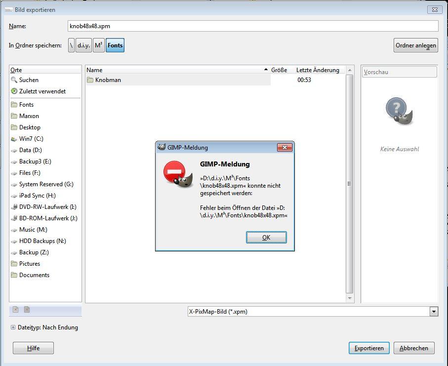
Great usefull tutorial!
I immediately started to create some bigger knobs.
Unfortunately GIMP shows this error when exporting the .bmp as a .xpm file

I also tried "XPMEdit" and "AutoImager" to convert the bitmap.
But converting these .xmp files leads to useless .inc files.
Do you know what could be the reason?
Or would you convert my .bmp files for me, please?
https://drive.google.com/file/d/0B-plp4B8LLvaUnlTaXJiTXhuWnM/edit?usp=sharing
Best regards
Marxon
-
Hi again!
...not sure, if we are talking about the same board then. u5 is the mems-sensor on page 36 of the discovery-manual. u5 is not getting 2v5 at all! its u7, the audio-codec, that needs the 2v5. but if you have removed c1 and c20 already, i cant see, where the short comes from.:blush: :blush: :blush:
Right again.
Maybee U5 does not become hot anymore because in meanwhile it is completely destroyed... :sweat:
hopefully you have ordered not just one discovery-board! i have 2 of them which i use with different configurations, as im using different lcd-types. the other advantage of that is, that you have always one on the shelf in case the other gives up..:-)Unfortunately not.
In general i should work more carefully... (dear SIDs, please rest in peace)
I have a additional LPC17 core but, because the lack of memory it is also only used to connect a different display.
Hopefully i will receive the STM324 board soon.
Greetz,
Marxon
-
Hi mono.
Thanks for your reply.
I noticed that U5 was getting hot, it is the only part which get's 2,5V from U3.
So I removed U3. Now U5 stays cold.
I also removed C1 and C20 unfortunately the short circuit remains.
You are right, the board is not very expensive. Another one is already ordered but this
means one week idleness
Best regards
Marxon
-
Hi all!
While working on my Midibox NG, I was careless for a moment and powered the STM32F4 core with too high voltage. :cry:
Now it seems that something is faulty on the STM Discovery board because there is a short circuit
between the GND and 5V pins (4 ohms).
My first thought was to check diode D1, D2 and D3, but they are OK.
Now i guess U1 or U3 might be have been destroyed but before i start to desolder them,i first want to ask if somebody might better know what to check .
Thanks a lot for your help! :thumbsup:
Best regards
Marxon -
I guess later you will need one or more DINs anyhow :)

LED digit issue
in MIDIbox NG
Posted
I made four 2-digit displays (so 8 digits total) each display gets controlled via a CC.
CC101 display 1
CC102 display 2
CC103 display 3
CC104 display 4
Now i want them to show only a specific set of values.
For example:
3.2.
1.6.
1.4.
4
32
So i created two different MAPs for first and the 2nd digit.
Here is the ngc code:
Display 1, 2 and 3 work like expected except the 2nd digit of display 4.
During troubleshooting i removed the MAP parameters from all events and
expected that both digits of display 1-4 will show the same.
Again display 1, 2 and 3 work like expected except display 4.
This is what you can see in the video.