

Flying Panther
-
Posts
91 -
Joined
-
Last visited
Content Type
Profiles
Forums
Blogs
Gallery
Everything posted by Flying Panther
-
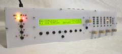
midibox fm strange characters
Flying Panther commented on Schrabikus's gallery image in Members Gallery
 Very nice, reminds me of the Waldorf synths (probably due to the matrix on the right side, but still) ;)
 -
Very nice!! How did you do the lettering? Is it red acrylic/metal with a black silk screen?
-
Plus that the older touchscreens in copiers mostly aren't very accurate, meaning you have to use big buttons that take up a lot of space and probably have to press hard. If I would go for a touch-screen, I would rather pay a bit more and get something good, then save some money and have no datasheet and unknown performance.
-
As my laptop isn't that fast, I'm not really up to date on the drumsoftware, but I really like NI's Battery 3. Basically it's a drumsampler that comes with a great collection of sounds. Of course a lot of acoustic kits, but also some very nice electronic kits. And it's a sampler, so you can always use (and do advanced edits on) other samples. I also have a Korg Electribe R, but for me those sounds are often too limited. After I got Battery, I mainly use the Korg as a stepsequencer/midicontroller to control Battery with. Other software I don't have much experience with, but heard good things about: Spectrasonics Stylus RMX for loop based drums FXpansion GURU (drum sampler / stepsequencer). I think they discontued GURU in favour of Geist..
-
Mouser parts have been shipped! Hopefully they will arrive soon..
-
And they're in! :)
-
-
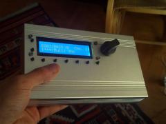 Great use of the HDD enclosure! Like it :)
 -
Really quick 4x20 display for the MB6582?
Flying Panther replied to Hawkeye's topic in Parts Questions
Too bad they don't offer the 4x20 in white as they do with some of the smaller sizes. White (if it is real white, not the blueish white) should give almost endless coloring options. -
For Sale: MBSID / MB6582 format with 6 SIDs (3 types)
Flying Panther replied to lucem's topic in Fleamarket
For the record, that might have had something to do with differences between the 6581, 8580/6582 and SWIN SID chips. Each type has different characteristics, so that might be causing the difference in sound. As for making a profit on a Midibox project, it's about the non-commercial (and thereby non-profit) spirit I guess.. Also has something to do with the time (and money) that was invested in such a project and (in this case) the small timewindow between the purchase and resell of the MB-6582. It gives a feeling that the effort that was put in making the box maybe isn't really appreciated and maybe you wanted to make some quick money (note: the feeling, I'm not saying it isn't appreciated!). -
Be sure to check that the audio and/or CV signals are not too high. I don't know the values that the chip can handle, but it would be a shame to fry the chip because of too high input signals.
-
Based on your information I'd say that the most simple version of the filter (mono filter that makes no use of the Mixer and VCA) should connect the SID output to the VCF Ext In (probably using a capacitor according to this Yahoo group topic). I'm not sure if CV Lin and Log should both be used or that you can choose between them. In the schematic they both are connected. If either Log or Lin is required, you can connect Cutoff CV Lin and Resonance CV to the AOUT_NG. Furthermore get the right capacitors for C1 to C4 and connect them between pin 15-18 and ground. Then connect -5V/GND/+5V to the right places and you're all set to go ;) Of course there's more to it, but I think if you can get that working, you can easily add functions to use the mixer and VCA as well (as you have more AOUT channels anyway). Also, you might find the schematics in this Poly 800 service manual more easy to read (higher resolution) and you might also find some usefull information in the DW-8000 service manual (as the DW-8000 uses the VCA after the VCF like you would expect, not as an additional VCF input attenuator).
-
I use a T.C. Electronic Konnekt 24D. I'm very pleased with the box, great pre-amps, nice DSP effects (reverb / channelstrip), can run without the computer as a mixer with the DSP effects (with limited control). But with only 4 analog in and out I will probably be expanding it with an 8x8 ADAT interface in the future. Coming from an M-audio USB Audiophile with small Phonic mixer the sound in recordings has improved a lot, but I think driver-stability could be improved on the Konnekt 24D. I believe T.C. has that sorted in their newer firewire interfaces though. When looking at a high quality firewire option, the MOTU 828mk3 might be an attractive alternative to my (future) combination of Konnekt 24D (or Impact Twin) + ADAT expansion.
-
For the Meanwell RPT-60B (sitting nicely on my desk now, thanks NorthernLightX!), some extra electronics are needed to provide me with additional smooting (which is mainly a precaution, as the power supply itself seems to have a lot of smoothing capacitors already), but more importantly needs to convert +12V into +9V for the 8580 Sids. This is the schematic I've come up with so far: I'm not sure if I implemented the latchup protection right, as I still don't really understand what's going on (I just copied from what was posted earlier). I will be using the modular SID boards, which will be connected to +5/AGND and +9 (which has no AGND to prevent ground loops on the SID-board). Now, if I understand correctly, to prevent latchup directly before the SID-chip, a diode needs to be placed between +9V and the AGND connected to the SID (coming from the +5/AGND rail). Also, I saw Shuriken used 1N4004 diodes in his schematic, but wouldn't a 1N4001 be sufficient as well (as 50V is quite a lot)? And could I maybe also use the 1N4148 here, or are those too small? Also, I'm thinking of using a metal film and a ceramic 0.1uF capacitor on each rail, as they both provide different smoothing caracteristics (so I figured they will complement eachother). And when using this schematic, is there any advice on the smoothing capacitors on the SID boards? I intend to leave the whole regulating circuit out on the SID-board (rectifier, capacitors, regulator, capacitors), but I'm thinking, would it help protect the SID in any way to leave the (last) 0.1uF capacitor on the 9V input of the SID? All thoughts are appreciated! :)
-
Sounds like they perform well. So, Lelon it is.. :thumbsup:
-
Hahaha, I had a good laugh while reading that schematic! Thanks! :)
-
Switchmode and switching is the same. Main problem is that the switching frequency can introduce noise in the audio channels. I found an interesting read on the difference between lineair and switchmode power supplies.
-
While searching for parts on Mouser, I discovered that most of the Xicon capacitors I had ordered before are now replaced with Lelon capacitors. See Mouser's statement here: http://www.mouser.com/pdfdocs/LelonXiconcaps.pdf. The statement is dated January 2010, but I could not find any information commenting on this. As both sizes and colors / lettering seems to be the same except for the Xicon / Lelon logo and specifications are identical, it looks like they are the same capacitors. Does anyone already have experience with the Lelon capacitors? In other words, can I just order the Lelon caps, or should I better look for other alternatives?
-
Nice tunes and congrats with knobs that complete the 6582! Sounds like I need to start working on my SID-boards again... :)
-
Normally, if your power supply fails or spikes, the voltage regulator will take the 'hit' and smooth the voltage to 9V as much as it can, therefore protecting your SID chip. Also it reduces noise/ripple which you may (or may not) hear back in your audio. The additional capacitors after the voltage regulator are there for the noise/ripple reduction as well.
-
Hou er rekening mee dat je je voor de Wiki even apart moet registreren. Dit is dus niet hetzelfde als waarmee je op het forum inlogt (alhoewel dat natuurlijk wel kan door bij allebei dezelfde gebruikersnaam te kiezen).
-
Very nice! The wooden panels make it an instant classic :)
-
A commercial SID synth that look damn familiar (seen on MESSE)
Flying Panther replied to stuartm's topic in MIDIbox SID
Definitely a bad move of ModeMachines / TBS. I can't see why this company even bothers, as SID's aren't that easy to come by and even more important, they could have guessed that someone would find out. And bad reputation is something you rarely get rid of... I hope they will come to their senses. -
JB-Weld is probably the best option here. When I re-read my suggestion for the supports it really sounds like a lot of work (and probably take some experimenting before it actually fits the way you want to). For the lettering/lining, maybe put the encoder's primary description above the knob, and the two secondary below it to save some space for the lining?
-
So it looks like we're all going to be energy efficient :) Makes sense, but let's hope better switch-mode PSU's will become more widely available for the special applications where the noise can be a problem.
-
The spacing between CC / SID etc button and LED's look good to me. Can't you fix the middle of the PCB's from the back? Or maybe put an aluminum bar between the outer screws (on the backside of the frontpanel), with a countersunk screw or tap-hole in the middle to fixate the PCB (will require other spacers and will be difficult to make, but it was just something that popped in my head).
-
Didn't know that.. Why would they be (or going to be) forbidden? Because switchmode is more efficient? Or am I missing some point here?