Smithy
-
Posts
1,240 -
Joined
-
Last visited
-
Days Won
28
Content Type
Profiles
Forums
Blogs
Gallery
Everything posted by Smithy
-
Not exactly sure how useful this info is, but I de-soldered the positive leg of this Diode and the issue seems to go away, ENC4 turns normally without lighting up the SW20's LED.
-
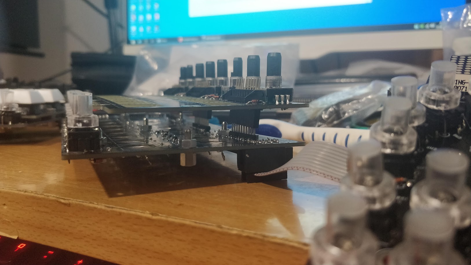
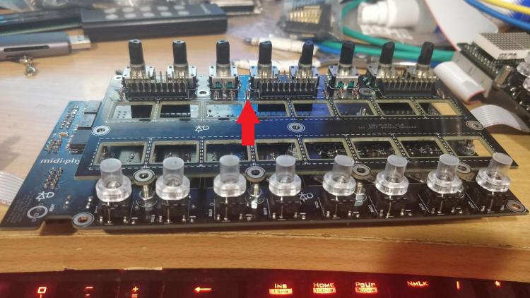
The RN pins are definitely not touching, here's a photo showing how far the PCBs are apart from each other with the headers: Shorting J1 Pin 8 to GND even at that distance causes SW20 to illuminate. Any advice or images of traces to help me find the short on the Enc Plate PCB? On the underside of the PCB there is quite a few spots where the silkscreen has been marked and copper is showing. No traces seem to be exposed however.

-
Still no short between ENC4 pins and J2 Pin 6. With the ENC Plate PCB installed when I short J1 pin 8 to GND the SW20 LED lights up and I get the following in debug, it includes touching the pin and releasing from it: [1036341.011] MBNG_MATRIX_NotifyToggle(1, 28, 0) [1036341.011] MBNG_DIN_NotifyToggle(2028, 0) [1036341.012] [EVENT] id=BUTTON:2028 hw_id=BUTTON:2028 bank=0 fwd_id=LED:2031 type=NoteOn value=0 label= [1036341.013] MBNG_DOUT_NotifyReceivedValue(2031, 127) [1036341.014] MBNG_MATRIX_DOUT_NotifyReceivedValue(2, 31, 127) [1036341.015] MBNG_MATRIX_NotifyToggle(1, 44, 0) [1036341.016] MBNG_DIN_NotifyToggle(2044, 0) [1036341.016] No event assigned to BUTTON hw_id=2044 [1036341.020] MBNG_MATRIX_NotifyToggle(1, 60, 0) [1036341.021] MBNG_DIN_NotifyToggle(2060, 0) [1036341.021] No event assigned to BUTTON hw_id=2060 [1036341.024] MBNG_MATRIX_NotifyToggle(1, 12, 0) [1036341.024] MBNG_DIN_NotifyToggle(2012, 0) [1036341.025] [EVENT] id=BUTTON:2012 hw_id=BUTTON:2012 bank=0 fwd_id=LED:2016 type=NoteOn value=0 label= [1036341.026] MBNG_DOUT_NotifyReceivedValue(2016, 127) [1036341.027] MBNG_MATRIX_DOUT_NotifyReceivedValue(2, 16, 127) [1036341.029] MBNG_MATRIX_NotifyToggle(1, 36, 0) [1036341.030] MBNG_DIN_NotifyToggle(2036, 0) [1036341.030] No event assigned to BUTTON hw_id=2036 [1036341.033] MBNG_MATRIX_NotifyToggle(1, 52, 0) [1036341.034] MBNG_DIN_NotifyToggle(2052, 0) [1036341.034] No event assigned to BUTTON hw_id=2052 [1036341.038] MBNG_MATRIX_NotifyToggle(1, 4, 0) [1036341.038] MBNG_DIN_NotifyToggle(2004, 0) [1036341.039] [EVENT] id=BUTTON:2004 hw_id=BUTTON:2004 bank=0 fwd_id=LED:2015 type=NoteOn value=0 label= [1036341.040] MBNG_DOUT_NotifyReceivedValue(2015, 127) [1036341.041] MBNG_MATRIX_DOUT_NotifyReceivedValue(2, 15, 127) [1036341.042] MBNG_MATRIX_NotifyToggle(1, 20, 0) [1036341.042] MBNG_DIN_NotifyToggle(2020, 0) [1036341.043] [EVENT] id=BUTTON:2020 hw_id=BUTTON:2020 bank=0 fwd_id=LED:2024 type=NoteOn value=0 label= [1036341.044] MBNG_DOUT_NotifyReceivedValue(2024, 127) [1036341.045] MBNG_MATRIX_DOUT_NotifyReceivedValue(2, 24, 127) [1036341.060] MBNG_MATRIX_NotifyToggle(1, 20, 1) [1036341.060] MBNG_DIN_NotifyToggle(2020, 1) [1036341.062] [EVENT] id=BUTTON:2020 hw_id=BUTTON:2020 bank=0 fwd_id=LED:2024 type=NoteOn value=127 label= [1036341.062] MBNG_DOUT_NotifyReceivedValue(2024, 0) [1036341.063] MBNG_MATRIX_DOUT_NotifyReceivedValue(2, 24, 0) [1036341.070] MBNG_MATRIX_NotifyToggle(1, 20, 0) [1036341.070] MBNG_DIN_NotifyToggle(2020, 0) [1036341.071] [EVENT] id=BUTTON:2020 hw_id=BUTTON:2020 bank=0 fwd_id=LED:2024 type=NoteOn value=0 label= [1036341.072] MBNG_DOUT_NotifyReceivedValue(2024, 127) [1036341.073] MBNG_MATRIX_DOUT_NotifyReceivedValue(2, 24, 127) [1036341.080] MBNG_MATRIX_NotifyToggle(1, 12, 1) [1036341.080] MBNG_DIN_NotifyToggle(2012, 1) [1036341.082] [EVENT] id=BUTTON:2012 hw_id=BUTTON:2012 bank=0 fwd_id=LED:2016 type=NoteOn value=127 label= [1036341.082] MBNG_DOUT_NotifyReceivedValue(2016, 0) [1036341.083] MBNG_MATRIX_DOUT_NotifyReceivedValue(2, 16, 0) [1036341.088] MBNG_MATRIX_NotifyToggle(1, 12, 0) [1036341.088] MBNG_DIN_NotifyToggle(2012, 0) [1036341.089] [EVENT] id=BUTTON:2012 hw_id=BUTTON:2012 bank=0 fwd_id=LED:2016 type=NoteOn value=0 label= [1036341.090] MBNG_DOUT_NotifyReceivedValue(2016, 127) [1036341.091] MBNG_MATRIX_DOUT_NotifyReceivedValue(2, 16, 127) [1036341.186] MBNG_MATRIX_NotifyToggle(1, 44, 1) [1036341.186] MBNG_DIN_NotifyToggle(2044, 1) [1036341.186] No event assigned to BUTTON hw_id=2044 [1036341.192] MBNG_MATRIX_NotifyToggle(1, 52, 1) [1036341.193] MBNG_DIN_NotifyToggle(2052, 1) [1036341.193] No event assigned to BUTTON hw_id=2052 [1036341.197] MBNG_MATRIX_NotifyToggle(1, 4, 1) [1036341.197] MBNG_DIN_NotifyToggle(2004, 1) [1036341.198] [EVENT] id=BUTTON:2004 hw_id=BUTTON:2004 bank=0 fwd_id=LED:2015 type=NoteOn value=127 label= [1036341.199] MBNG_DOUT_NotifyReceivedValue(2015, 0) [1036341.200] MBNG_MATRIX_DOUT_NotifyReceivedValue(2, 15, 0) [1036341.201] MBNG_MATRIX_NotifyToggle(1, 20, 1) [1036341.201] MBNG_DIN_NotifyToggle(2020, 1) [1036341.203] [EVENT] id=BUTTON:2020 hw_id=BUTTON:2020 bank=0 fwd_id=LED:2024 type=NoteOn value=127 label= [1036341.203] MBNG_DOUT_NotifyReceivedValue(2024, 0) [1036341.204] MBNG_MATRIX_DOUT_NotifyReceivedValue(2, 24, 0) [1036341.205] MBNG_MATRIX_NotifyToggle(1, 36, 1) [1036341.206] MBNG_DIN_NotifyToggle(2036, 1) [1036341.206] No event assigned to BUTTON hw_id=2036 [1036341.210] MBNG_MATRIX_NotifyToggle(1, 60, 1) [1036341.211] MBNG_DIN_NotifyToggle(2060, 1) [1036341.211] No event assigned to BUTTON hw_id=2060 [1036341.215] MBNG_MATRIX_NotifyToggle(1, 12, 1) [1036341.215] MBNG_DIN_NotifyToggle(2012, 1) [1036341.217] [EVENT] id=BUTTON:2012 hw_id=BUTTON:2012 bank=0 fwd_id=LED:2016 type=NoteOn value=127 label= [1036341.217] MBNG_DOUT_NotifyReceivedValue(2016, 0) [1036341.218] MBNG_MATRIX_DOUT_NotifyReceivedValue(2, 16, 0) [1036341.219] MBNG_MATRIX_NotifyToggle(1, 28, 1) [1036341.219] MBNG_DIN_NotifyToggle(2028, 1) [1036341.221] [EVENT] id=BUTTON:2028 hw_id=BUTTON:2028 bank=0 fwd_id=LED:2031 type=NoteOn value=127 label= [1036341.221] MBNG_DOUT_NotifyReceivedValue(2031, 0) [1036341.222] MBNG_MATRIX_DOUT_NotifyReceivedValue(2, 31, 0) This does not happen without the Enc plate PCB installed / connected. I also tried doing it with the arduino headers installed to separate the PCBs further like in the photo below, and I do get the events and SW20's LED lighting up still. So this should rule out a short between components touching on both boards. Shorting J1 Pin 9 to GND has no effect. Would I be right in thinking there's a short somewhere on the ENC Plate PCB?

-
So i tested for shorts between all encoder legs of ENSW4 and the pins of J2 - nothing. Disconnected the plate PCB and shorted pins 9 and then 10 of J1 to GND. Nothing comes up on Debug. (I even removed the comment # character from the DIN line in seq_r.ngc and tried a second time just in case.
-
I set it up in RH mode (from left to right: Core -> LE MEC -> LE MEC RH -> JA PCB ) and loaded up seq_r and the issue remained. I commented out the DIN MATRIX line in seq_r.ngc for the RH PCB and this is the result of turning ENCSW4 clockwise one detent with set debug on: [ 657.687] MBNG_DIN_NotifyToggle(36, 0) [ 657.688] No event assigned to BUTTON hw_id=36 [ 657.702] MBNG_ENC_NotifyChange(12, 1) [ 657.703] [EVENT] id=ENC:12 hw_id=ENC:12 bank=0 fwd_id=DISABLED:0 type=CC value=0 label= [ 657.708] MBNG_DIN_NotifyToggle(36, 1) [ 657.709] No event assigned to BUTTON hw_id=36 I noticed SW20 did not light up this time when turning. The Mattias LEDs Common Cathode are still desoldered, so not sure if these would light up in this column with DIN commented out. I presume I was not meant to comment out DOUT_MATRIX? Thanks!
-
 Looking Great!
 -
I've just replaced IC3 and IC4 on the LEMEC RH PCB and no luck unfortunately. Damn you short, where are you!
-
No shorts found on between any of those resistors, and on the IC4 pins. Checked the values of R14 / R15 and theyre correct - 1K. I reflowed the pins of IC4 and no luck. This issue doesn't seem to be an obvious one whatever it is!
-
Fluxtest ran fine I'm pretty sure when I had the superflux CC and Mattias switches soldered. Only interesting thing I've spotted so far is that R24 and R25 seem to be inverted on the Le MEC RH board. I.E. I'm measuring GND on the opposite side compared to the resistors on the Le MEC 1.0 pcb. But maybe the orientation is just flipped between Boards? All the diodes are in the correct orientation also.
-
The resistor networks are definitely soldered correctly: Any suggestions for a noob on how to read voltages in the appropriate places without frying the boards? :P I reflowed all points you mentioned but no luck. Can't thank you enough for the help.


-
Been looking for shorts while waiting for the 165 ICs to arrive and still can't find anything. However I decided to temporarily add arduino headers to J-1 to 3 to see if something on the ENC Plate PCB was shorting out something on the Le MEC RH PCB. Basically the PCBs would be further apart. No such luck there, i'm beginning to think the short is somewhere on the Le MEC RH PCB. I've been checking the small the tiny vias for shorts also but no luck there. Its driving me round the bend but I'll persist. I'll update the thread when the 165s arrive and I replace them.


-
Pushing the Encoder button on ENSW4 behaves as it should, no extra inputs or anything. I tried reflowing the IC3 pins with hot air but no luck. I also desoldered the Mattias switches and took pics of the boards: Le MEC RH 1.3R top side: ENC Plate 1.0 Bottom side: I'm stumped! Going to order a replacement for IC3 anyways.


-
I get quite a lot with one single turn of the encoder (from one detent to the next detent - clockwise in this example.) [196444.183] MBNG_MATRIX_NotifyToggle(1, 20, 0) [196444.183] MBNG_DIN_NotifyToggle(2020, 0) [196444.184] [EVENT] id=BUTTON:2020 hw_id=BUTTON:2020 bank=0 fwd_id=LED:2024 type=NoteOn value=0 label= [196444.185] MBNG_DOUT_NotifyReceivedValue(2024, 127) [196444.186] MBNG_MATRIX_DOUT_NotifyReceivedValue(2, 24, 127) [196444.188] MBNG_MATRIX_NotifyToggle(1, 36, 0) [196444.189] MBNG_DIN_NotifyToggle(2036, 0) [196444.189] No event assigned to BUTTON hw_id=2036 [196444.192] MBNG_MATRIX_NotifyToggle(1, 52, 0) [196444.193] MBNG_DIN_NotifyToggle(2052, 0) [196444.193] No event assigned to BUTTON hw_id=2052 [196444.196] MBNG_MATRIX_NotifyToggle(1, 4, 0) [196444.196] MBNG_DIN_NotifyToggle(2004, 0) [196444.197] [EVENT] id=BUTTON:2004 hw_id=BUTTON:2004 bank=0 fwd_id=LED:2015 type=NoteOn value=0 label= [196444.198] MBNG_DOUT_NotifyReceivedValue(2015, 127) [196444.199] MBNG_MATRIX_DOUT_NotifyReceivedValue(2, 15, 127) [196444.201] MBNG_MATRIX_NotifyToggle(1, 28, 0) [196444.201] MBNG_DIN_NotifyToggle(2028, 0) [196444.202] [EVENT] id=BUTTON:2028 hw_id=BUTTON:2028 bank=0 fwd_id=LED:2031 type=NoteOn value=0 label= [196444.203] MBNG_DOUT_NotifyReceivedValue(2031, 127) [196444.204] MBNG_MATRIX_DOUT_NotifyReceivedValue(2, 31, 127) [196444.206] MBNG_MATRIX_NotifyToggle(1, 44, 0) [196444.207] MBNG_DIN_NotifyToggle(2044, 0) [196444.207] No event assigned to BUTTON hw_id=2044 [196444.210] MBNG_MATRIX_NotifyToggle(1, 60, 0) [196444.210] MBNG_DIN_NotifyToggle(2060, 0) [196444.211] No event assigned to BUTTON hw_id=2060 [196444.214] MBNG_MATRIX_NotifyToggle(1, 12, 0) [196444.214] MBNG_DIN_NotifyToggle(2012, 0) [196444.214] [EVENT] id=BUTTON:2012 hw_id=BUTTON:2012 bank=0 fwd_id=LED:2016 type=NoteOn value=0 label= [196444.215] MBNG_DOUT_NotifyReceivedValue(2016, 127) [196444.216] MBNG_MATRIX_DOUT_NotifyReceivedValue(2, 16, 127) [196444.244] MBNG_ENC_NotifyChange(12, 1) [196444.245] [EVENT] id=ENC:12 hw_id=ENC:12 bank=0 fwd_id=DISABLED:0 type=CC value=2 label= [196444.270] MBNG_MATRIX_NotifyToggle(1, 60, 1) [196444.270] MBNG_DIN_NotifyToggle(2060, 1) [196444.271] No event assigned to BUTTON hw_id=2060 [196444.274] MBNG_MATRIX_NotifyToggle(1, 12, 1) [196444.274] MBNG_DIN_NotifyToggle(2012, 1) [196444.276] [EVENT] id=BUTTON:2012 hw_id=BUTTON:2012 bank=0 fwd_id=LED:2016 type=NoteOn value=127 label= [196444.276] MBNG_DOUT_NotifyReceivedValue(2016, 0) [196444.277] MBNG_MATRIX_DOUT_NotifyReceivedValue(2, 16, 0) [196444.279] MBNG_MATRIX_NotifyToggle(1, 28, 1) [196444.279] MBNG_DIN_NotifyToggle(2028, 1) [196444.281] [EVENT] id=BUTTON:2028 hw_id=BUTTON:2028 bank=0 fwd_id=LED:2031 type=NoteOn value=127 label= [196444.281] MBNG_DOUT_NotifyReceivedValue(2031, 0) [196444.282] MBNG_MATRIX_DOUT_NotifyReceivedValue(2, 31, 0) [196444.283] MBNG_MATRIX_NotifyToggle(1, 44, 1) [196444.284] MBNG_DIN_NotifyToggle(2044, 1) [196444.284] No event assigned to BUTTON hw_id=2044 [196444.288] MBNG_MATRIX_NotifyToggle(1, 4, 1) [196444.288] MBNG_DIN_NotifyToggle(2004, 1) [196444.289] [EVENT] id=BUTTON:2004 hw_id=BUTTON:2004 bank=0 fwd_id=LED:2015 type=NoteOn value=127 label= [196444.290] MBNG_DOUT_NotifyReceivedValue(2015, 0) [196444.291] MBNG_MATRIX_DOUT_NotifyReceivedValue(2, 15, 0) [196444.293] MBNG_MATRIX_NotifyToggle(1, 20, 1) [196444.293] MBNG_DIN_NotifyToggle(2020, 1) [196444.294] [EVENT] id=BUTTON:2020 hw_id=BUTTON:2020 bank=0 fwd_id=LED:2024 type=NoteOn value=127 label= [196444.294] MBNG_DOUT_NotifyReceivedValue(2024, 0) [196444.296] MBNG_MATRIX_DOUT_NotifyReceivedValue(2, 24, 0) [196444.297] MBNG_MATRIX_NotifyToggle(1, 36, 1) [196444.298] MBNG_DIN_NotifyToggle(2036, 1) [196444.298] No event assigned to BUTTON hw_id=2036 [196444.301] MBNG_MATRIX_NotifyToggle(1, 52, 1) [196444.301] MBNG_DIN_NotifyToggle(2052, 1) [196444.302] No event assigned to BUTTON hw_id=2052 The blobs around IC is the reflection of flux against the light, the light makes it look like solder. Its looking like I'll need to desolder the Mattias switches and inspect the top side. I'll wait til you've looked at the debug messages. Thanks again Andy.
-
So the issue with the LeMEC RH I'm having is that when I turn ENCSW4 clockwise or anti-clockwise, the 2 superflux LEDs and MEC switch SW20 light up directly below when turning that encoder. As soon as i stop turning the encoder the LEDs go off . If i keep it in between the detents the leds stay on. I think keypresses are being registered in MIOS studio also. Any ideas where to check on the bottom side of the PCB or the far left hand side of the top PCB before I go de-soldering Mattias switches again? Here are some pics: I must point out that I lifted the top pad for R13 so ended up soldering the resistor lead to the trace directly I believe. See pic below: I'm getting continuity between that leg of R13 and pin 3 aka QD output of IC4 - SN74HC595. But i presume thats okay? Just thought it was worth mentioning.


-
I mentioned it early that some pins were bent on that IC and I desoldered it and tried to straighten them but snapped that pin clean off the IC! So it will have to be replaced as the copper sticking out of the IC absolutely tiny and I doubt i can bridge it.
-
Andy can you confirm that pin 13 in IC5 is linked to Encoder 6 before I order the replacement SN74HC165? Thanks!

-
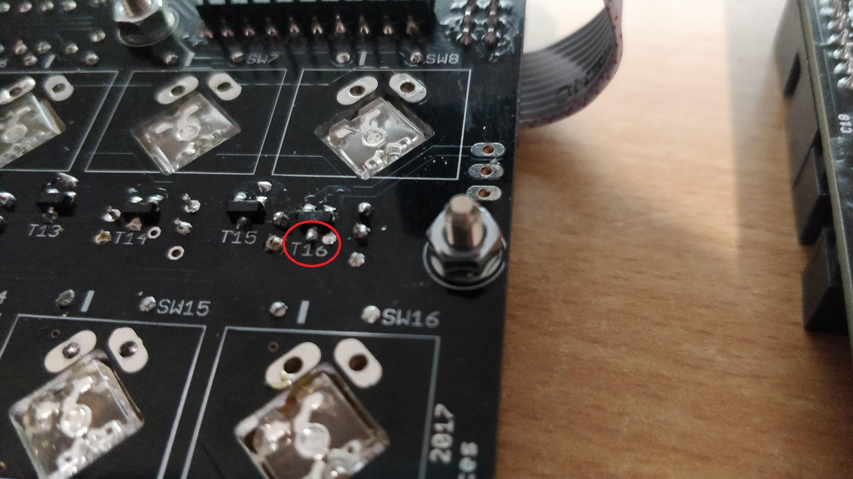
I trusted my cutting of the RJ leads and went ahead and de-soldered all the Mattias switches in the Lemec PCB. Turns out there was a short between the bottom leg of T16 and the unused pad to the right of it! Thank god for my desoldering station otherwise this would have taken much longer, if i could even do it all with a manual pump! I owe you an expensive beer when I'm done! I'm going to test the superflux leds now with the diode test on my multimeter in case the heat has damaged them. I also found an issue in the RH Lemec board earlier. Turning Encoder 4 lights up the LEDs in the 3 switches below it. I'll post more detail on that later.

-
fixed the image.

-
Fixed the picture of the underside of the board.
-
Also I seem to have rectified the LED on switch 24 lighting up when the buttons of the other MEC switches are pressed at least. I think there was a bridge between one of the transistors an unused pad.
-
I tried soldering a bridge between pin 15 and pin 16 of IC4 and no luck. The 4 leds still light when seq_l is loaded. I presume thats exactly what I was meant to do? I just have to remove the switch caps and light shields to be able to separate the boards again I presume? Cheers!
-
Update: Soldering the BAT54 diode on top of T7 did not fix the issue with the 4 superflux LEDs staying on.
-
I think I've spotted something off. T7 on the bottom of the PCB has no BAT54 diode piggy backed on top of it. I must have missed it. I'll solder one on now.
-
Here's an updated pic of the underside of the LEMEC board, hopefully the problem is on that side or I have some serious dismantling to do!
-
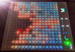
Having some further issues with the finished LeMEC 1.0 (left hand) board unfortunately. When I load seq_l the Superflux LEDs of SW4, SW8, SW12, and SW16 light up and stay on. All switches work fine including Switches SW 17 to 24. But when I press any switch from SW17 - SW23, the LED of SW24 also lights up dimly when it shouldn't. The respective switches press light up fine. I thought IC5 - the 74HC165 was the culprit as some pins were bent so I de-soldered it. Unfortunately I broke pin 13 / pin C clean off while trying to straighten it. The issue with the Superflux LEDs staying on when they shouldn't be existed before this btw! I re-soldered the chip again hoping that it was unused, but now Encoder 6 is unresponsive when turning it clockwise / counterclockwise. At least I presume pin 13 is responsible for this encoder, i could be wrong. No big deal there, I can buy another 74HC165 off ebay and replace it. Any ideas where the issue may be with the Superflux LEDs being lit up? The LEMEC RH board works perfect, and this LEMEC 1.0 board has the same issue wether LEMEC RH is connected or not. The fluxtest script works fine too, the LEDs that are lit up just turn yellow when the colour sequence passes. Also the other leds turn red when pushing down on the econders and of course the naughty 4 change to yellow when they're pressed.