

latigid on
-
Posts
2,516 -
Joined
-
Last visited
-
Days Won
147
Content Type
Profiles
Forums
Blogs
Gallery
Everything posted by latigid on
-

LoopA V2 Introduction, Features & Support Thread
latigid on replied to Hawkeye's topic in MIDIbox User Projects
Hi Robert, I've seen it happen that the SD slot can be soldered with too much heat and this can kill things. How was your soldering of it? Check for continuity back to the 407v breakout pins, here's a convenient pinout of the SD card from the top: NC NC NC PA6 0V PA5 +3v3 0V PA7 PB2 NC I would suggest not to solder the three leftmost pins. You can also check for flux residue or shorts there. Care to upload photos of your work? Best, Andy -
Glad to hear! Enjoy your sFM! You can get some cool sounds out of it but I found programming is not 100% straightforward.
-
Check back to the Core pin and whether the PIC is socketed properly or has adjacent shorts, check the interconnection header pins/socket.
-
LoopA V2 Introduction, Features & Support Thread
latigid on replied to Hawkeye's topic in MIDIbox User Projects
Yep, the L4 superellipse caps were very popular and we sold the last sets over the weekend. More caps inbound but will of course take their time at the moment. Ordering a full kit would be possible if you were happy with the old clear-style caps, still some of those around. For LED soldering, you can just mount the LEDs flush against the PCB. They will not fit through the case cutouts anyway. One user wrapped his panel LEDs with heatshrink (Schrumpfschlauch) to block light from neighbouring positions. It's a personal preference though; some like the effect of LED mixing. Best, Andy -
Mouser 517-929834-07-36-RK is one of the longest "standard" headers but only single row. Check the datasheet on the Mouser page and you will find other parts. None of the longer dual-row header 929710 are stocked apparently. But you could use a pair of single-row strips, which is what we do for the LoopA.
-
Maybe then check the data signals reach the shift register? You can cross-reference the PIC Core and DOUT schematics: http://ucapps.de/mbhp/mbhp_doutx4.pdf http://ucapps.de/mbhp/mbhp_core_v3.pdf If in doubt you can also disconnect the sandwich and run wires directly from the Core pins.
-
Pics are a bit blurry, but it looks like the LEDs have the correct orientation. You should be able to scope a (probably) 1/8 pulse on the LED cathodes anodes if that column's LED is illuminated. Likewise, you should see an alternating (but up to 1/8) pulse on the transistor base. Do the transistors follow the expected pinout? When uploading the hex file did you specifically choose the sammich one or "normal" MIDIbox FM?
-
Can you get any normal LED function? Touch up the soldering on everything to do with the LEDs (pin headers, ICs, caps, resistors etc.), also check LEDs have the correct polarity .
-
Hi, These encoders should be decent, so I wouldn't think the encoder had gone bad. Rather, there might be an interconnection issue. The 9th encoder is connected to pins 4 and 5 of J1, so check that you get good contact there. If the pins don't reach far enough into the through-board header you might get an intermittent contact. Check all solder points too as you might have a dry joint etc. Best, Andy
-
MIDIO 128 Midifyin an Allen Organ to work with Hauptwerk
latigid on replied to LawrenceL's topic in MIDIfication
Sorry, didn't see your message as the notification settings were broken for a while. I can't say anything about Hauptwerk but you should be able to monitor debug events in MIOS Studio. I would try to diagnose the DIN/DOUT functions and matrices first at the hardware level. -
I'm no NG expert, but what is the exact event/ the parameters used? Do you set specific ports for example? Maybe post the config and somebody could help.
-
Many thanks for reporting and I'm glad it works! Is the hub also connected to the computer and sending data that way? There is an OTG startup sequence where the devices have to decide who's the boss. Maybe things don't make it that far if there's too much going on with the datalines. Just speculation!
-
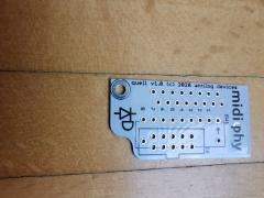
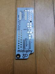
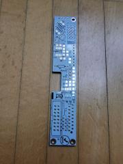
Sorry, I managed to upload one twice. The quell PCB functions as a terminator, so you clamp unused inputs to 0V.
-
© 2020 latigid on
-
I recently designed Eurorack versions of DIN and AIN, still need to test but hopefully in the next few weeks, @Antichambre maybe you should start your own thread as to not mix up things, thanks. Have fun! Andy
-
© 2020 latigid on
-
© 2020 latigid on
-
© 2020 latigid on
-
© 2020 latigid on
-
Not sure I understand fully. You adjust the trim pot to get the scaling as linear as possible, i.e. the trimmer should be set so each octave step is as close as possible to the target voltage. Then you use the SEQ encoders to finely adjust for each volt setting. The DAC can't drive negative bits, so there is a limit to the lowest setting. But the remaining octaves should be very linear. Did you already see @Hawkeye's video on the calibration procedure?
-
Sounds like it could be a software bug, in which case the following thread is the place for it: http://midibox.org/forums/topic/13137-midibox-seq-v4-release-feedback/?page=61
-
One other idea: you could try plugging directly into the 407v board (mini USB cable). Here is the schematic, maybe some of the jumpers are helpful? https://www.waveshare.com/w/upload/5/58/CorexxxV-Schematic.pdf
-
Some Mouser parts have longer lead times at the moment. Here's a few suggestions: 595-SN74HC595DR -> 595-SN74HC595D (just non-reel packaging) 490-SJ1-3535NG -> 490-SJ1-3535NG-BE (blue) 594-K104K15X7RF53L2 -> 75-1C10X7R104K050R 806-KCDX-5S-S2 -> reichelt https://www.reichelt.de/din-socket-5-pin-semi-circular-printed-version-mabp-5s-p11178.html Conrad https://www.conrad.de/de/p/cliff-fm6725-din-rundsteckverbinder-buchse-einbau-horizontal-polzahl-5-schwarz-1-419666.html CR1206-JW-331ELF SMD resistors just use a 220R or 71-CRCW1206330RJNEAC WP154A4SUREQBFZGW Kingbright LED, tricky to find a frosted one, but basically any generic CC RGB LED will do, or a bicolour 3-pin is fine but normally not available in "nice" green. *** Feel free to post your suggestions or if you can't find a part.
-
There's a few settings in the HWCFG to check e.g. (search "fast") # the speed value for GP encoders which is used when the "FAST" button is activated: ENC_GP_FAST_SPEED 3 # Auto FAST mode: if a layer is assigned to velocity or CC, the fast button will be automatically # enabled - in other cases (e.g. Note or Length), the fast button will be automatically disabled ENC_AUTO_FAST 1 # the speed value for the BPM encoder which is used when the "FAST" function is activated ENC_BPM_FAST_SPEED 3 Can you check if altering these changes things to your liking? Of course, some features might have been "broken" by hard-coding functions. In the Wilba SEQ version, there was one common fast button, no matter what encoder was pressed. In the v4+ we have all of the encoders on dedicated DIN inputs (matrix) to allow for different customisation.
-
The v4+ does nothing different to your previous method: the ID pin is grounded when in OTG mode and floating otherwise. Maybe check pin PA10 is correctly grounded on the wCore PCB/breakout? Cabling issue or missing contact through the 2x25 pinheader? Perhaps the value for R3 on the USB board is too conservative and 100R would be better.
