latigid on
-
Posts
2,516 -
Joined
-
Last visited
-
Days Won
147
Content Type
Profiles
Forums
Blogs
Gallery
Everything posted by latigid on
-
Hey, is this an original build? If you want a SEQ V4, I highly doubt anybody will trade down to a non-working V3. Presumably you have a veroboard CS and not the Wilba PCB installed? The good news is that you can swap out the Core and have a V4 right away using all of the original control surface. There is a page on uCapps.de detailing the upgrade.
-
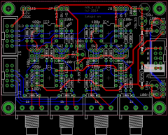
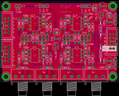
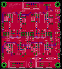
Now with board-mounted pots; the 1k value shouldn't significantly affect the gain factors. The pads could be bridged if they weren't needed.
-
© 2014 latigid on
-
Salut, tu as des pics stp?
-
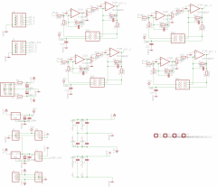
Well... of course the pot can't drive an op amp as the impedance is too high... I'll move them to the output. Anyone know off hand recommended pot values? I.e. what's good to drive the GPIO correctly? Think again: the first op amp stage is a better place to put the pot.
-
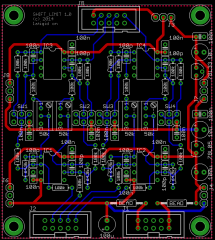
I routed up a four-channel board with different power options. Just need to move a few labels around.
-
© 2014 latigid on
-
© 2014 latigid on
-
© 2014 latigid on
-
Seems to work in simulation. (link to Falstad)
-
Can the free DOUT pins be assigned to LEDs for the seven clock outs? It would be nice to have some visual indication here. My current idea is to have a front panel with the following controls: Clock out with clock led (8th socket for clock in, LED for this too?) CV in CV range switch (0-5, 0-10, -5-+5). Input attenuator for CV. Possibly this can also act as a fixed 0-5 V control (i.e. just a pot) if nothing is plugged into the CV input. Feature request: CV inputs can act as momentary or latching "switches" to enable outputs or operate internal controls. As a crude example, see Doepfer's A-151 sequential switch module. (This just distributes a signal to one of four outputs stepped through by a clock.) http://www.doepfer.de/a151.htm
-
Case(s) in point from MI: BAT54S diodes in Frames: Rail-to-rail op amp (AD8534) in Braids: Rail-to-rail op amp (MCP6004) in Tides (also Grids): Rail-to-rail op amp (MCP60042) in Edges: The diodes are a bit easier to integrate but their leakage current could mean the ADC inputs go a bit too far over the allowed limits. The op amps will ensure that any over/undervoltages will be clipped to the supply (3.3 V and ground) but the input range is limited to about 0.025-3.275 V, or about 0.06-3.292 for the 8534. Any preferences?
-
What are you looking to trade? Where are you located?
-
Hey FFW, Of course, I don't have to buy them. And I'm not after the BLM, so I can't fulfil your package sale. I do think it's a little wrong to profit off Smash's PCBs though, even if you add convenience for somebody. Best of luck with your sale, looks like you have a buyer already!
-
Hey, I ended up buying 100 from RS and giving the rest to the workshop. But thanks! :flowers:
-
Cheaper to buy the F4 Core from SmashTV, including shipping. STMF4 discovery is 13€ from mouser. SEQ CS PCBs are unobtainium at the moment, so you might have an angle. When I bought mine it was 30 USD.
-
Hmm, seems like the forum's reverted to a backup?
-

Yup! It had erased/chosen not to display a bunch of PMs too. Good thing I got those in the mail.
-
-
Any spare 4-40 screws going?
-
You can put anything through a recitifier (AC or DC) but you have to deal with the diode drop in both cases. Study the PCB layout on the wiki and draw a circuit diagram for a start. Also keep in mind that several of the pins in the DIN connector are not used... If you're serious (and crazy) about using two separate supplies there's nothing stopping you having two different configurations wired to separate pins of the socket.
-
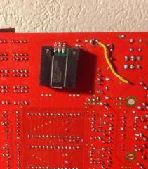
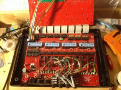
Here's a partly finished MB-6582 with the previously mentioned cables: These wires look like solid tin to me. They are quite rigid, but they conform to a bendy shape. No problems thus far!
-
Alt, do you mean 1 amp draw for a regular MB-6582 or with your switching solution? I am using your recommended 5 V switching voltage regulator (http://www.mouser.ch/ProductDetail/Texas-Instruments/78SR105HC/?qs=sGAEpiMZZMtwaiKVUtQsNWWYJJUUxYbPRFCRyYymPj0%3D) where I am drawing about 200 mA with all LEDs lit. This is without SIDs so far, hopefully this weekend! I found the back was a better place to mount it, this way the 7809 can heatsink on the huge ground plane. This works better for the 5 V pinout too, where the (redundant?) smaller smoothing caps are now on the output. To Blatboy: as Wilba designed this with a C64 brick in mind, you have to solder a few jumper wires to get the power in off a single supply. You can for instance use the DIN7 socket and forgo redesigning the back panel. Check this thread for Altitude's work: Just a note: your rectified 9 VAC will actually be near to 12.6 VDC once smoothed out. 9 VAC * 1.4 = 12.6 VDC rectifying and smoothing 12.6 - 2*0.7 = 11.2 VDC two diode drops Should be enough for a 7809.
-
-