latigid on
-
Posts
2,516 -
Joined
-
Last visited
-
Days Won
147
Content Type
Profiles
Forums
Blogs
Gallery
Everything posted by latigid on
-
Excellent! How have you mounted the front panel components? MBOTW candidate ;)
-
A desoldering iron: a vacuum combined with a soldering tip. A reflow station might also work but it would be best to heaksink the chip while you do it. I got my SIDs NOS from Wilba, so no problems for me :).
-
8 bit LCD mode?
-

[S] DB-25 AOUT breakout board and gate level shifter PCBs
latigid on replied to latigid on's topic in Fleamarket
All boards have been shipped now. If there is any more interest, feel free to post here and I will do another run (with a few tweaks) provided there are sufficient numbers. -
I hate to say this, but this is one of the reasons that resale of MIDIBoxes was discouraged... You didn't build it yourself and so you have no idea what could be wrong now. What is the extent of your electronics knowledge? Can you use a multimeter? Solder? Upload sysex via the MIOS terminal?
-
Maybe this helps? I ended up buying Mouser part 571-FSP-22A-8, for a soon to be completed MB-6582.
-
Anonymous bidding is never a good idea, it's probably best if you come up with a value for it. E.g. start with your parts, case cost and go from there.
-
Search "JB Weld" or "JBWeld" in the forum, it's a good way of fixing M3 metal hex spacers/standoffs to metal panels. Plastic is a bit different, the projects here often use Ponoko/Formulor cases that "samich" or compress together. In this way the components are PCB mount that makes things a lot easier.
-
[S] DB-25 AOUT breakout board and gate level shifter PCBs
latigid on replied to latigid on's topic in Fleamarket
One left! -
[S] DB-25 AOUT breakout board and gate level shifter PCBs
latigid on replied to latigid on's topic in Fleamarket
Two orders sent today, one board is left and one payment is pending. -
Absolutely!
-
[S] DB-25 AOUT breakout board and gate level shifter PCBs
latigid on replied to latigid on's topic in Fleamarket
3 boards left, two orders shipped today and two payments pending. Parts list is now on the original thread. -
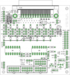
Parts list: Resistors: 11 220R 19 10k I used metal film 1% but the tolerance is not critical. 1 5k single turn trimmer (horizontal adjust) Caps: 1 1uF tantalum (C2) *** please observe the correct polarity! *** 3 100n monolithic (C1, 3 and 4, non polarised although C1 is marked as so) Semis: 1 LM317 variable voltage regulator (TO-92 package) 2 SN7407 open collector hex non-inverting buffer 2 14 pin DIP sockets if you wish Connectors: 100 mil SIL headers: 5 2-pin 11 3-pin 8 2-way jumpers, or replace with wire links if you don't want to select the gate voltage 100 mil DIL headers: 1 16-pin 3 10-pin As noted, the clearance is too tight for three 10-pin DIL sockets. Sorry about that! I used a 34-pin with two gaps of two pins. 1 DB-25 connector I used this one from RS. It seems as there are two standards: 0.318" and 0.590". You want the 0.318". EDIT: I just noticed that the + sign for C2 went wandering in the board picture above! Please observe proper polarity, which is correctly marked on the PCBs Note: +/-12 or 15 V can be used.
-
© 2014 latigid on
-
[S] DB-25 AOUT breakout board and gate level shifter PCBs
latigid on replied to latigid on's topic in Fleamarket
4 boards left, two orders will be sent out tomorrow and I am awaiting one payment. It's a simple enough build, but I will put up a BOM on the original thread. In particular, there are two different standards for DB-25 PCB sockets. It's the Euro one I think, but let me check before you buy parts. Thanks! -
[S] DB-25 AOUT breakout board and gate level shifter PCBs
latigid on replied to latigid on's topic in Fleamarket
4 PCBs spoken for, 5 left. The postage is a bit more than I thought, it is about 4€ In Europe... -
Please see this thread: I have nine spare boards, so please PM if you would like one or more. They will cost 6 EUR each, plus standard letter postage of about 1 EUR for Europe and 3 EUR to the US. Other postage options can be discussed of course.
-
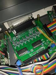
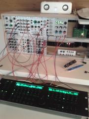
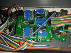
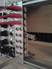
Okay, it works! Sorta... So this is my one year old level shifter/DB-25 breakout project. It works! +/- 12 V is coming in off the Eurorack bussboard and powers both the open collector 7407 buffers and the AOUT_NG mounted directly above. This simplifies the SEQ power supply a great deal. +5 V is taken from J5C at the moment, but there's also a 2-pin connector for this. 8 channels of CV connect directly to the DB-25 port; I used a 16-way ribbon, but a samich connection is also possible as the spacing lines up perfectly. The CV and gates are wired to two rows of 3.5 mm sockets. You can adjust the gate voltage near to the +12 V rail (10.3 V seems to be the maximum you can get out of an LM317) and the triggers fire as expected. Although I just soldered in links in my case, you can switch between +5 and +V gates with jumper pins. I didn't test MIDI OUT 3, DIN sync or the LPC connector as of yet, but they are wired up according to schematics. There's room for a buffer (SMT) if somebody wants to try it with AOUT J19 data. TK recommends differential line drivers however. Silly me, I neglected to put the correct spacing for the J5 connectors :rolleyes: Fortunately I left 100 mil spacing, so it works fine with one 34-way IDC from a STM32 F1 Core comprising J5A, B and C. It might also work with one 10-way cable underneath the board? I have nine spare boards, so please PM if you would like one or more. They will cost 6 EUR each, plus standard letter postage of about 1 EUR for Europe and 3 EUR to the US. Other postage options can be discussed of course.
-
© 2014 latigid on
-
© 2014 latigid on
-
© 2014 latigid on
-
© 2014 latigid on
-
© 2014 latigid on