

rbv2
-
Posts
105 -
Joined
-
Last visited
-
Days Won
5
Content Type
Profiles
Forums
Blogs
Gallery
Posts posted by rbv2
-
-
Hi all,
would it be possible to implement saving mutes of the individual drum instruments (drum Tracks) when using s&top function in phrase mode?
Have a nice weekend
rbv2
-
thanks for your reply.
the m16 looks promising but I'm afraid i not fully understand the capabilities or how to set it up. would it be possible to make a standalone midi-router from it?
probably have to wait until it's more prepared for soldering by numbers :)
thanks
-
hello,
is it possible to get boards for this project or is it planned to offer it in midiphy-shop? I am very interested... would like to be able to route 32inputs to 16outputs (ports).
thanks
rbv2 -
have found something..
https://mechanicalkeyboards.com/shop/index.php?l=product_detail&p=477
-
1 hour ago, latigid on said:
Can we see? Would be the first SEQ with them!
What tools did you use? A wire puller?
i pulled them by hand. is there a special tool?
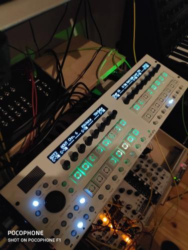
the picture does not match the actual impression. one can clearly distinguish which steps are selected.
-
 3
3
-
-
pulling off the caps from the matias switches is quite tough. a lot of force is needed.
The new caps looking great and help with the light diffusion.
thanks
-
1
-
-
just ordered

-
1
-
-
now i'm curious :)
-
1
-
-
24 minutes ago, Hawkeye said:
@slo great build, congrats!

Regarding key cap alternatives to the clear ones on the standard builds, we might have something cooking in the lab, that could be introduced soon :).
:D yesss, can't wait. after a while of usage i find it a little bright too.
-
2
-
-
On 12.3.2020 at 9:17 PM, slo said:
Another successful build. Thanks to all involved for such a great design and realization of this sequencer. I followed the build videos and that kept me on track. The only problem I had was of my own doing, mixing up the resistor networks then getting erratic output on the first seq_l test. Hot air and swapping the resistor networks around fixed this. Thanks to @Antichambre for those great looking keycaps too. Looking forward to more great things from the Midibox team.
Edit: I did have the odd inversion of colors on the beat LED, I had red on measure green on beat, a change of values in the config file HWCFG fixed that.

i like the keycaps a lot :D
-
2 hours ago, latigid on said:
I'm not 100% sure what you mean with very long lengths. Does it remain when the gate length is set to glide? Video?
when sending out triggers from AOUT Ch16 and then select in the parameter layer "lenght" i can change the lenght of the trigger/gate from 1% to Glide
at 1% - no trigger
at 2% - sporadic trigger
from - 3-20% steady trigger
from - 21-100 % double trigger with increasing distance (21% narrow / 100% wide)
glide - only the first trigger
before we fixed the grounding issue i got double triggers starting at 5% and other problems but now i'm pretty shure those are gates and not triggers making some modules being triggered at the beginning and the end of that rectangular pulse.
-
thanks a lot, it's working much better now also the random triggers when inserting cables are gone now :)
only get double triggers on very long "lenght" settings wich i assume is normal behavior. are those real triggers or very short gates?
thanks @Hawkeye and @latigid on for your support and patience
you deserve a beerbtw. where is the "buy hawkeye a beer" button?
-
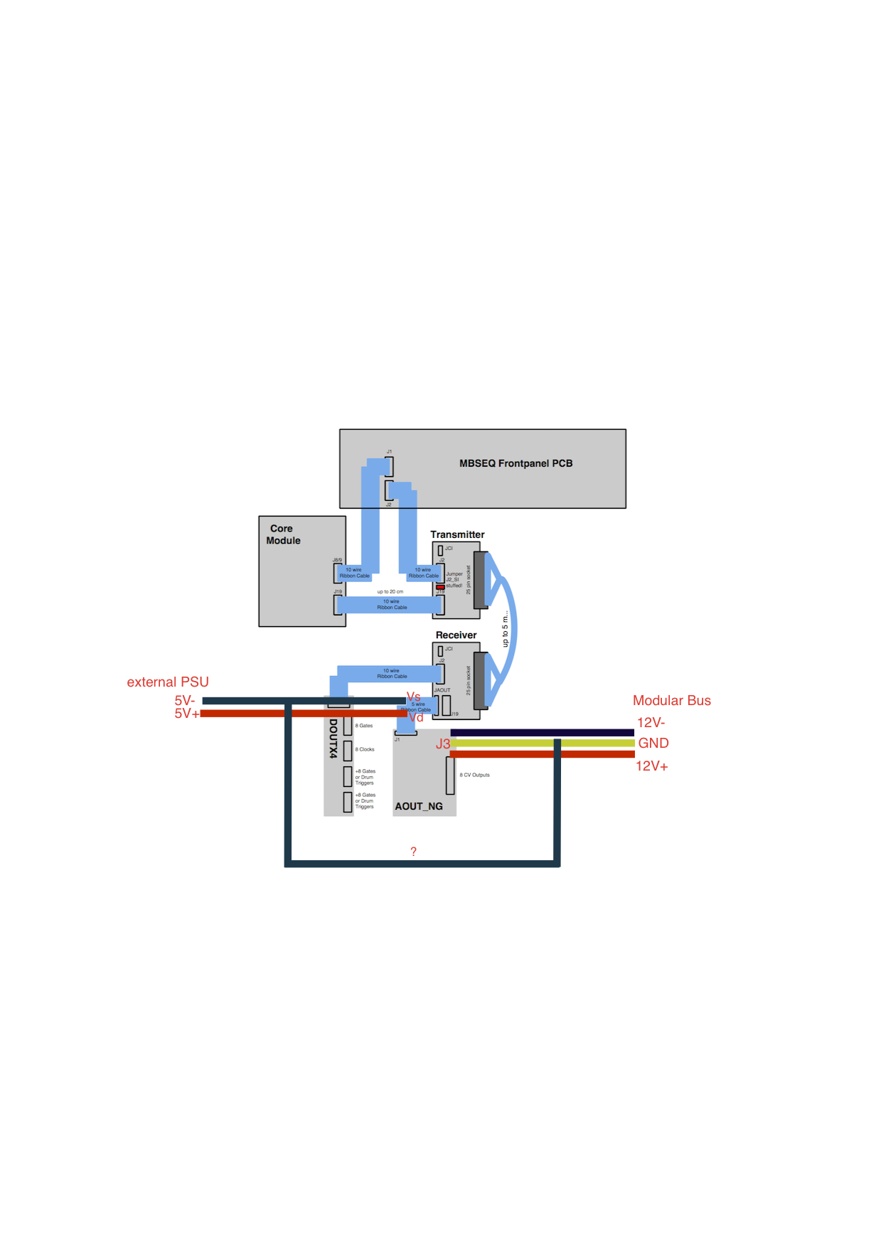
5 minutes ago, latigid on said:
Is the external PSU actually +5/-5V? So a 10V supply?
no, its 5V didn't know how write it correctly.
 8 minutes ago, latigid on said:
The 0V should be common rather than 0V to -12V. I think that's what your diagram shows, but the 0V of the PSU should connect to the yellowish wire on your diagram, not the black -12V
yes, isn't so well drawn but that's what I meant.
thanks. i try it and report
-
thanks!
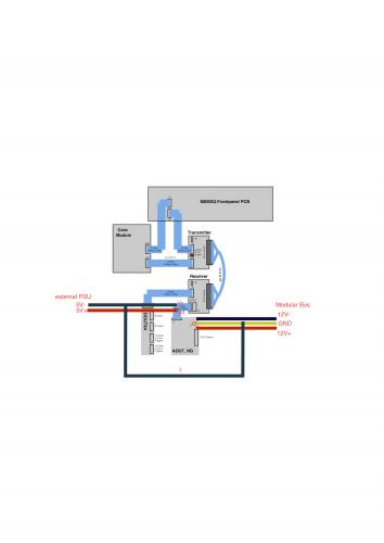
to be on the safe side, I made a drawing.
it shows my current wiring. the black line with the question mark shows how I understand it.
would that be okay?
thank you!
rbv2
-
hi latigid on,
thanks a lot for your answer.
- since i have made no changes in the HW Config beside setting the 1ms-option and SRs for clocks, gates & Trigger i would assume no
- all tracks muted except for the one sending triggers to CH16
- checked all cables visually again
- the resistance between 0V Eurorack and pin 2 of a Midi Socket oscillates between 1,8-2,5 Ohm
- no jumper in J3
- the double trigger only occours on some modules and depends on the setting of the length in the parameter layer, when length is 4% it's almost gone, it's acting like a gate..
- I'll try to do the tests in mios when I understand how it works
7 hours ago, latigid on said:If you use an external PSU you must connect the 0V together with the +/-12V PSU 0V common line. A metal panel is not a good (and some would say unsafe) method of achieving common 0V.
so the connection underneath the DAC is not sufficient then?
7 hours ago, latigid on said:I guess you are not using the +5V on the bussboard? But if you are, maybe you don't have +5V connected and the modules are being parasitically powered from the digital signals? (This is not good for CMOS btw.) Did you measure correct +5V on the modules?
yes, i am using an external power plug. i get 4,96V on J2 of AOUT NG and 4,96V on J19 of the Receiver
unfortunately I still have to wait for the scope..
thanks
rbv2
-
hi peter,
at the shematic i can see the point you refering to but there is no jumper or place for a pinheader.
yes i use the DOUT module for 8x Gate, 16x Trigger an 8x Clock the AOUT NG is for CV only.
a friend of mine will lend me his scope. but i don't have one right now.
thank you!
-
hi peter,
thanks a lot for you answer.
8 hours ago, Hawkeye said:Hola,
just tested the new dedicated midiphy eurorack modules, that are in the works - while i don't have a big modular setup, i measured and tested gate and trigger outs and had no issues (tested triggering the "Freeze" and the "Trig" functions on a MI Clouds and also measured signal outputs with a scope). Therefore, I would also expect maybe a common ground problem on your side? Have you grounded the external PSU and the LineDriver Receiver to the modular/rack common ground?
at the moment i have wired 12V+/- and GND directly from a doepfer bus board to J3 of the AOUT NG the external psu is in the middle of the cable from JAOUT of the receiver to J1 of the AOUT NG. (Vs & Vd) . by common ground do you mean i should connect the Vs line of 5V PSU to the GND of J3 at the AOUT NG? all the jacks (gate, trigger, cv) are connected to ground and since the panel is made of aluminium the gnd of both psu's is connected.
8 hours ago, Hawkeye said:The new euroceiver module (left in the pic below, which still uses handmade paper/epoxy panels for fit-testing) has a built-in voltage regulator, that allows generating the required 5v from the +12V modular rail, which will spare you the external psu and would not require you to send the +5v down the DB25 cable from the SEQ, which might be problematic.
unfortunately i saw the information about the new modules too late. i would rather use them but i had already bought all the parts and ordered a panel at schaeffer..

i have also learned that the 5v on the doepfer boards are not there at all although it is written on it

thanks!
-
20 hours ago, latigid on said:
Maybe create another post as it's not really a v4+ problem?
done :)
-
hi all,
after testing i found an minor issue with my breakout-box. everything is working as intended but i get annoying double triggers on some modules. when i connect the same modules to my robokop sequencer or other trigger source everything is fine. could it be a grounding issue?
the +/-12V for the AOUT NG is coming from my eurorack and the +5V for AOUT NG and the LineDriver Receiver from an additional psu. the external psu (5v) is in the middle of the ribbon cable between AOUT NG and the receiver as suggested by latigid on. i also enabled the 1ms trigger but it makes no difference.
when using the same trigger on another module it works so i guess i can rule out the double trigger is coming from the sequencer itself.
please help
rbv2
-
hi all,
after testing i found an minor issue with my breakout-box. everything is working as intended but i get annoying double triggers on some modules. when i connect the same modules to my robokop sequencer or other trigger source everything is fine. could it be a grounding issue?
the +/-12V for the AOUT NG is coming from my eurorack and the +5V for AOUT NG and the LineDriver Receiver from an additional psu. the external psu (5v) is in the middle of the ribbon cable between AOUT NG and the receiver as suggested by latigid on. i also enabled the 1ms trigger but it makes no difference.
please help
rbv2
-
thanks for the update. looks great
-
On 14.3.2019 at 0:08 AM, latigid on said:
SRs: JA: 1,2; lemec_L: 3,4; lemec_R: 5,6,7,8,9, so try starting at SR10 for the gates.
you were right. SR10 (gates) , SR11 (trigger 1-8), SR 12 (trigger 9-16).
thanks again, it's working now
-
Just now, latigid on said:
SRs: JA: 1,2; lemec_L: 3,4; lemec_R: 5,6,7,8,9, so try starting at SR10 for the gates.
I'll try that tomorrow.
thank you for the quick reply -
hello all,
could anyone please help me with the breakout box for my seqv4+?
after first testing the AOUT NG is working fine but i don't get any gates/clocks/triggers from the DOUT. in the hwcfg i have enabled SR 3 for gates, 4 for clock signals, and 5-6 for drum triggers also the setting for the 1ms pulses is enabled.
when shift register nr4 is enabled all the leds on the left LEMEC board lighting up
 so i'm guesing it's maybe the wrong shift register.
thanks
Midibox v4+ for Sale / Saxony-Germany
in Fleamarket
Posted
Hello all
Selling my midibox sequencer including breakout box. The sequencer is fully functional, from a non-smoking household. Has never been used for live performances, only studio use.
The breakout box is a bit obvious DIY but fully functional. You need a free slot in the modular system for the +-12V power supply.
Selling price 1350,-€.
best regards
rbv2
https://www.ebay-kleinanzeigen.de/s-anzeige/midiphy-sequencer-v4-midibox-stepsequencer/2241157248-74-4257