

nlate
-
Posts
68 -
Joined
-
Last visited
Content Type
Profiles
Forums
Blogs
Gallery
Everything posted by nlate
-
Tutorial #029: Fast Scan Matrix for velocity sensitive Keyboard
nlate replied to TK.'s topic in MIOS programming (C)
Hi Thorsten, I looked into the code at app.c of tutorial #29 and have some (may be silly) questions: Why don´t you use a debounce fct. ? Is this not necessary, because today´s keyboards (Fatar etc.) use bubble contacts.If I want to use 16bit (u16) array variables, to save valuable RAM space, does this cost more exec cycles on an ARM core? (I am an injured Intel x86 guy :pirate:)What about timestamp wraparound? (after 15 days running the tutorial) Thanks in advance for responding. Kindly Regards Jo -
Tutorial #029: Fast Scan Matrix for velocity sensitive Keyboard
nlate replied to TK.'s topic in MIOS programming (C)
Hi Thorsten, Thanks for correcting the Readme.txt Aah, I forgot, that's the nature of SPI, Regards, Jo -
Tutorial #029: Fast Scan Matrix for velocity sensitive Keyboard
nlate replied to TK.'s topic in MIOS programming (C)
Hello Thorsten I don´t understand your calculation. As far as I can follow there are 2 ser. DOUT register for the rows an 1 ser. DIN register for the columns which lead to 16 x 8 = 128 contacts or 64 early & final contacts pairs. This means for me 64 keys with velocity sensing. Supposing (16 bits [for DOUT] + 8 bits [for DIN])/row * 0.64 uS/bit * 16 rows = 246 uS plus some spare processing time leads to the aforementioned 300 uS scan time but for 128 contacts. Where is my error in reasoning? Regards Jo -
Monster 72 Fader MBHP_MF_NG implementation. Best approach?
nlate replied to finis's topic in MIDIbox HUIs
Hi Finis Before you start with the (more expensive) PGFM 8160. There is one small detail on mot. Alps K faders which makes them perform better than the P&G faders. A small plastic guide mounted on the pulley side of the Alps Fader makes it more responsive when the fader motor changes its direction. This tiny small part makes the control SW much more strait forward (less deadband / hysteresis on direction change) Regards Jo -
Monster 72 Fader MBHP_MF_NG implementation. Best approach?
nlate replied to finis's topic in MIDIbox HUIs
Hello Finis, A very ambitious project you have in mind. Following questions should be checked in advance of buying 72 motorized Alps K faders: Do the Calrec consoles have VCAs for channel volume control? Because the mot. Alps K Faders only have Linear 10k tracks. a log. tapper is not available as motorized. K type afaik. So, your PGF 8000 fader should be of type PGF8110/8112 or 8160 type (Lin. or VCA type)The fixing holes of both fader types are 120 mm appart, so no problem but the overall length of the ALPS K Fader is larger on buttom (pulley) and top (motor). so ensure that you have enough space in the consoles channel strip fader area.Just my 2 cents. Regards Jo -
Hi Ilmenator Sorry for the confusion Just for clarification: I know about the slow MIDI transfer rate. My interest (lack of knowledge) is more on the Core MIOS32 side. With " the serial protocol bus nature" I mean the IIC bus. So I reformulate my question: Does the scheduler of the MIOS allow processing of only one IIC per 10uS time slot or are the 10uS per IIC Input device caused by the IIC "arbitration" if more than one IIC MIDI module has MIDI data on its input, ready to send to the Core?. I hope this makes my previous question more clear. Regards Jo
-
Hello Thorsten just a question about IIC MIDI Input Iatency: Does this mean for e.g. 4 IIC MIDI Inputs a latency of 4x10 uS = 40 uS has to be added, independent of the amount of the MIDI msgs on the IIC MIDI Inputs or is this just for the worst case scenario caused by the serial protocol bus nature, if all 4 IIC MIDI have data to transfer to the CORE module? Regards Jo
-
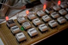 Hi Schrabikus, Looks very nice (even on Veroboard) What type of buttons and KeyCaps are you using?
 -
Dear Thorsten, the 4 PCB and 4 MagJacks arrived yesterday. Thank you very much (thanks also for soldering the MagJacks :thumbsup:)! Regards Jo
-
Auf dem Bild ist aber die "Billigversion" ALPS RSAOK11VP mit Standard Motor NICHT 'coreless' zu sehen. Coreless ist ALPS RSAOK11W und sieht so aus: http://www.ucapps.de/mbhp/mf/final/rsaok11w.jpg Gruss Jo
-
Proposal for MBHP_IIC_MIDI transfer protocol enhancements
nlate replied to nlate's topic in Design Concepts
Thanks Thorsten for your immediate response. Your answer to my 1st question rel. the USB MIDI protocol makes sense, I have also to admit: Never change a winning team! Your comments to the 2nd question are reasonable. Btw I used the trick with the lookup table in IIC_CMD.asm for dispatching the incomming IIC commands. Your concerns about using a branchtable (the 256 byte page limit) are true and for that purpose I used markers for the begin and end of the table to verify no page overlap in the map file (s. IIC_CMD_TableBegin & IIC_CMD_TableEnd). I know, that there is a chance to trap in this pitfall. But the map file should be checked anyway if anything gets to be changed. Jo -
Proposal for MBHP_IIC_MIDI transfer protocol enhancements
nlate replied to nlate's topic in Design Concepts
I did some PIC Assembler programming in the last few weeks, implementing nearly all routines used for the protocol proposal. The initial proposal needed some modifications and enhancements during implementation. (s. attachment) I have to admit that I was not able to burn the code to a real target device up to now. This will follow in the next week(s) But the current state of the asm code is assembled successfully (s. *.map file) I could also post the sources here as *.zip. Imho my code is not ready to be put in the svn repository. What is missing a.t.m. is the trigger input handling via interrupt for scheduled MIDI Realtime Commands on MIDI output One of my preconditions (leaving the HW untouched) in my initial post could no be fullfilled completely: - to make use of the trigger input via interrupt, the Port pins need to be rearranged to make a PortB pin available. (only PortB pins can generate interrupts) If this function is not needed by the host and if not more than 4 IIC_MIDI devices are used, only one jumper has to be set to connect RA5 to GND (J1: Vs o-o X3) If scheduled command processing on MIDI output and/or more than 4 devices, a rearrangement of the Jumpers and insertion (soldering) of 4 additional 10k Pull-Up resistors has to be done: 1. use RB6 as low-active trigger Input (ID0 on J3) 2. install 4 x 10k Pull-Up Resistors on the solder side of the PCB 2.1 RA2 -> 10k -> Vdd (e.g. IC1: Pin1 -> 10k -> Pin14) 2.2 RA3 -> 10k -> Vdd (e.g. IC1: Pin2 -> 10k -> Pin14) 2.3 RA4 -> 10k -> Vdd (e.g. IC1: Pin3 -> 10k -> Pin14) 2.4 RA5 -> 10k -> Vdd (e.g. IC1: Pin4 -> 10k -> Pin14) 3. Use J1 as IIC Address terminal (Address (0x10..0x1f): 3.1 Vs o-o X0 -> ID0 3.2 Vs o-o X1 -> ID1 3.3 Vs o-o X2 -> ID2 3.4 leave X3 open! Here some questions mainly addressed to Thorsten about his implementation: 1. Why must the 0xff command for entering the IIC Command state be handled by a state machine? Imho it is a violation of the USB protocol anyway, because MIDI Reset cmd (0xff) should be sent as 0x0f (single byte) and not as 0x03 (three-byte sys-comm msg). 2. Prot.asm: the table access fct. for e.g. EXPECTED_BYTES_COMMON_TABLE suggest that the tables reside in the EEPROM area. But the tables reside in the normal programm area. Is there not a simpler and faster way to access them? Comments and suggestions wellcome! Jo IIC_Midi_Cmd Protocol5.txt map.txt -
I use a Roland M-480 Rack mixer connected to a creamware Scope PCI Card with analog I/O. (24 Stereo Inp. -> 2 x Stereo Outs; 6 Aux rails, 4x AF, 2x Pre/AF selectable) All my rack Synths are hardwired to the Inputs; PCI Card In is feed by SubOut. PCI Card Out -> Inp. 47/48 (last stereo Inp.) Main Out goes to the Monitor LS As you already mentioned, any kind of analog HW mixer is essential for PC-less jamming /playing. Even my wife can activate & play my rig :rolleyes:(she's a music teacher). This is essential for me to justify frurther investments :wink: One big advantage over conventional tabletop Desk is its vast functionality in its small 6U 19" Rackspace. Regards Jo
-
Proposal for MBHP_IIC_MIDI transfer protocol enhancements
nlate replied to nlate's topic in Design Concepts
Thank you very much, Thorsten! This is the hardest part, as I'm not familiar with PIC assembler programming. I've always some tutorial sites open on my 2nd screen, when I (try to) code PIC assembler. Regards, Jo. -
Dear Thorsten, dear MIDIBOX community Since several months I have the idea of a sophisticated MIDI Patchbay/rtp-MIDI LAN device in my mind based on your beloved IIC-MIDI & MIOS32 Hardware platform. After some top-down and bottom-up mindgames, I started buttom-up by defineing a iic interface protocol for interconnection the STM32 Module with the iic midi IF. Motivation: The MIDIBOX IIC MIDI Module (s. http://www.ucapps.de/mbhp_iic_midi.html) can be enhanced to act as a pair of "intelligent" MIDI sockets, keeping away the computational load of basic MIDI protocol processing in a host as the CORE_STM32 Module. The MIOS32 based host then can then handle the more application specific tasks like a MIDI patchbay (eventually with a LAN Interface for processing the rtp-MIDI protocol stack) or a MIDI Sequencer like the current MIDIbox SEQ V4 (maybe V5). What would be nice to have as enhancement for the curent implementation: 1. Filter/Mute commands for MIDI IN and MIDI OUT to minimize transfer of unused commands on MIOS_IIC_ByteReceive and on MIDI OUT line: 1.1 MIDI Channel Voice msg 1.2 MIDI SYSTEM COMMON msg 1.3 MIDI SYSTEM REALTIME msg 2. Autonomous handling of Active Sensing without involving the host under normal operation conditions. (Active Sensing may be usefull to dectect cable breaks or unintended power losses in a networked remote environment) 3. Handling of Running Status on MIDI Input & Output 4. Exact same REALTIME Command execution on all MIDI Outs. Since the actual IIC implementation of the PIC 16F88 lacks of the broadcast address definition, this could be achieved by using a scheduled (delayed) command which is processed when a dedicated pin, common for all IIC MIDI modules is triggered by the host. 5. Prioritized processing of REALTIME commands at MIDI Input 6. PANIC (Sequence of All Notes off, Reset all controllers etc. on all MIDI channels) on MIDI Output. 7. Housekeeping commands. (Initialize, Bufferstatus, Reset) Preconditions for this protocol enhancement: - downward compatibility to the current IIC_MIDI transfer protocol - No violation of Thorsten´s inspiration from the USB MIDI specification. - use of the current hardware platform (s. http://www.ucapps.de...hp_iic_midi.pdf) - IIC addr. extension from 4 to 8 slave devices (maybe RA2?) on J1 - 1 additional interrupt generating input pin (maybe RA3?) on J1 as a common "execute" signal for scheduled MIDI Realtime Commands (s. below) Additional RAM resources used in PIC16F88 (1st guess): 1. MUTE Patterns 1.1 Channel Voice msg: 16 bytes 1.2 SYSTEM COMMON msg: 1 byte 1.3 SYSTEM REALTIME msg: 1 byte 18 bytes/direction => 36 bytes in unused GPR1 2. Additional SYSTEM REALTIME cmd handling 2.1 Prioritized REALTIME msgs: 4 x 1 byte 2.2 Scheduled REALTIME msgs: 4 x 1 byte 8 bytes in SHARED RAM area (73..7F) 3. Active Sensing Processing: ca. 4-8 bytes in GPR1 4. Additional states: ca. 4 bytes in SHARED RAM or GPR0 area Comments and suggestions wellcome! Regards Jo IIC_Midi_Cmd Protocol.txt
-
Hallo Jan, Hallo Nils Selbstverständlich dürfen MIDI Realtime Commands wie F8 jederzeit gesendet werden auch zwischen 3-byte Befehlen oder innerhalb eines Sysex Streams. MIDI Realtime commands sind immer 1byte Statusbytes mit gesetztem MSB. Sie haben immer Priorität, sonst entsteht ein MIDI Clock jitter (MIDI wackelt auf der 31k25 Leitung schon schlimm genug. Details dazu in der "MIDI 1.0 Detailed Specification" Seite 35 Gruß Jo
-
Hi nILS My boards arrived yesterday Thanks a lot for your effort Regards Jo
-
40x2 Green-on-Black Optrex Displays - ORDERING INSTRUCTIONS
nlate replied to fussylizard's topic in Bulk Orders
Hi Chris I got my 4 Displays yesterday. Thanks again for your effort Regards Jo -
Hi Robin Last weekend I had found some time to evaluate my latest toy, a LOGICPORT LOGIC ANALYZER from http://www.pctestinstruments.com/. I have a cheap Fatar TMK88, with aTP9 Keybed and a PIC16F74 build in, as a candidate to see the Logicport in action. Fatar actually uses the BR0..BR10 & MK0..MK10 signals as strobes (active low signals) and monitors the data lines T0..T7, which are connected to a parallel PIC port via 2k2 pullups. The data lines represent 8 keys, because the BRx strobes scans the break (upper) switches, and the MKx strobes scans the make (lower) switches. 1. Transition from untouch -> key-press: when Data Out: BRx 1->0: => Data In: T0..7 1->0. 2. Before reaching the lower key position: when Data Out: BRx 1->0: => Data In: T0..7 = 0. 3. Reaching the lower key position: when Data Out: BRx 1->0: => Data In: T0..7 = 0; when Data Out: MKx 1->0 => Data In: T0..7 1->0. The scanning procedure for the whole keyboard is repeated every 400 usec. The clever thing is that only the BR0..10 scanlines are strobed as long as no key-presses are detected. If any key-press is detected (BR0..BRx..BR10; BRx 1->0 => T0..7 1->0) the related MKx will also be activated in the next scan period like BR0, BR1..BRx, MKx, BRx+1..BR10. Some Timing Data BRn -> BRn+1 : 6 usec BRn, MKn, Tn low (0) time: 1.5 usec BR0..BR10 scanning duration (no key pressed): 60 usec BR0..BRx,MKx..BR10 scanning duration (1 key pressed): 66 usec => 60 usec + (count of MK strobes)*6 usec Scanning procedure repeat time: 400 usec So processing can take place in 400 usec - 22*6 usec: 268 usec These are my 2 cents to the never ending but enlightening key velocity scanning discussion in this fantastic forum. Regards Jo