

mokkinger
-
Posts
18 -
Joined
-
Last visited
Content Type
Profiles
Forums
Blogs
Gallery
Everything posted by mokkinger
-
Thanks Luke, thats great News! I prob.twisted an unselected Step, and the ramp looked quite Strange - but the function itself Sounds great! Will check that asap. Best, Mark
-
Hi Thorsten, I did the upgrade of my Seq V4 to 0.83 yesterday, and noticed that the "Select ALL"-function behaves different - in fact, when in Step-Mode, Note-Layer, and I select ALL and turn an encoder _some_ steps change, but others dont; is this intended to be or a bug? did you add any other feature to the "ALL" button? thanks & sorry, if this was explained earlier here - I read most of the thread, but didnt find an answer... br, Mark
-
hi thorsten, thanks for your reply; sorry for posting this issue twice, as I wasn´t sure if anybody still checking this thread I opened a new one with my question in the SEQ forum... and, yes, I used only the USB power of my imac yesterday. then nils told me this could be insufficient, and so I plugged the seq into another 5V supply - but without any success on the CV out... still no reading on the DMM :( I am kind of lost now cause I dont have any other core lying around to swap and see where the actual fault might be. on J19 on the core32 I have 4,9V and 3,9V on two of the Pins but there isnt any voltage change when changing the Note Values on G1T1... is this because the DMM is too slow to monitor these values? and, yes, sending the AOUT_NG to you would be a great option - would you do the check for me, so I can maybe sort out the problem and order a new module at smashTV...? let me know if I should mail it to you, ok? regards, mark
-
SEQ V4 and AOUT_NG: 5V Power necessary to work?
mokkinger replied to mokkinger's topic in MIDIbox SEQ
sad but true - it wont work. still no CV output on the AOUT_NG Module. I tried everything again, connected the core to an extra 5v power, connected the ground pads of both power supplies, checked the solder joints twice again, nothing. is there any other way to check if the TLV is okay? any possibility to check if the output on J19 of the Core32 Module is correct, when routing the G1T1 to AOUT? As I dont have any other midi box core module I cant check it in any other combination, and, if there isn´t any possib. to test the AOUT_NG itself for full function OR test the Core32 if its output on J19 is fine? please help as I am really stuck here... :( thanks! mark EDIT: as thorsten replied on my question from yesterday in the troubleshooting forum we can maybe close this thread here as the topics are similar... -
SEQ V4 and AOUT_NG: 5V Power necessary to work?
mokkinger replied to mokkinger's topic in MIDIbox SEQ
:) okay, thanks! I already expected this answer... so then I´ve got to build another PSU module; hope it will work then as it should. -
Hi Folks, my SEQ V4 has an AOUT_NG module attached, that wont put out any CV. After checking the wiring and the correct setup of the Seq/Tracks, I was wondering if I need to attach a +5V source to the SEQ V4 in order to run the AOUT_NG, or is the USB Power enough? I do have the +-12V attached to the AOUT though... thanks for your help, regards, mark
-
hi, sorry to step into your thread grizz, but it seems like we are both having the same problem with our Seq V4 and the AOUT_NG Module; I also have a full working Seq V4 from Wilbas Bulk order, configured correctly to work with the AOUT_NG, set up G1T1 correctly, connected the AOUT_NG like shown in the hookup diagram, Checked the Module for all voltages, but cant read any voltage on the CV output. already checked all the above, nothing wrong up to that point, just didn't run the IO check application yet... but while reading this, I am wondering, did you get it to work in the meantime grizz? and, as I have the SeqV4 running via USB Power on my imac, do I need to attach a 5V source in order to power the AUOT_NG? or will it also work with the USB Power supplied? maybe this is my fault...?! really hoping to get this module working, but I dont have any clue where to search for further faults... :( do you have any tipps for me? thanks & regards, mark
-
MB-SEQ V3/V4 Control Surface PCB and matching case
mokkinger replied to Wilba's topic in MIDIbox SEQ
Hey Julian, thanks again for the panel! the green looks fantastic, and I am almost finished with my seq4; Great Job you did on this! Just to ask again as I still don´t have any acrylic screens in front of my displays: id you do some of these? and if yes, would you sell a pair of those? or did anyone else do screens that snap-fit into julians / wilbas Frontpanel? best, mark -
Has anybody ever thought about using an audio signal from your DAW (a trigger pulse) as an input, so the Mac/PC can be the Master, but the midi clock is generated by the clockbox, based on the trigger pulse? Could the AIN module be used to insert a pulse signal from the DAW? that would be my favorite solution, as I really depend on the PC as master, but the Midi timing of ableton & logic really sucks... (there is a comercial solution from innerclocks, the sync-lock, quite expensive...)
-
the bulk order already has happend, I recieved my stuff about 2 weeks ago. was about 120 US$. the wilba-frontpanel maybe seems a little more advanced to build, but it´s really cool thing and documented quite ok! if you can go for it, don´t know if wilba does a second batch...
-
my MB 808 is finally finished. great sound, great sequencer. love the midibox stuff!
-
-
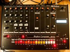
From the album: mokkinger MB 808
-
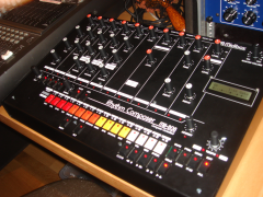
From the album: mokkinger MB 808
-
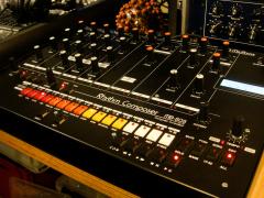
From the album: mokkinger MB 808
-
MB-808: additional Triggers, 15V to trigger SH-101
mokkinger replied to mokkinger's topic in MIDIbox SEQ
ok, so that would convert the trigger to +15 V so it can trigger an external Instrument like the 101? I just built an OpAmp with a 4558D, and now I have +13,88 V on the trigger out, but this doesn´t work. :-( also with this OpAmp turned on I can´t hear any trigger sound on the headphone anymore... i will try to activate the Ext. triggers now, and connect one with the two transistor schema, hopefully that will work; what I am not sure about is the assignment of the shift register pins to the Ext Triggers. The default.asm says that Shift Register 1, 4 and 7 (for th accent only) are used, and on Shift register 4 there are some Pins not used (pin 2 and 6) . I guess there could be some spare pin for the Ext 1 and 2 to fit... ? and do I have to compile a new hex-file after this? never done that kind of stuff before - help is really really apreciated!! :-) and where to go with the output of these pins? they go directly into R1 of the transistor scheme that TK posted? and the output is the trigger to go to the 6,3 mm jack? sorry for asking these noob questions, but I am still beginning with all this, and this seems to be really complicatd to me... i´m still not sure if I can handle all this... thanks for reply on this! mark -
MB-808: additional Triggers, 15V to trigger SH-101
mokkinger replied to mokkinger's topic in MIDIbox SEQ
ok, so i could also just build an OpAmp that drives the 5 v up to 15 V, right? Im not shure what the accent section of the MB-808 does, but as I remember it is a little more complicated than just an OpAmp... -
MB-808: additional Triggers, 15V to trigger SH-101
mokkinger replied to mokkinger's topic in MIDIbox SEQ
ok cool. so first of all I should edit the config file to activate the 3 ext triggers, right? and after that I guess I could find these trigger signals on the shift registers by checking for the voltage, right? I thnik I saw empty pins at the shift register, but I´m not shure if theses are the right ones... and do I understand you right, I need to build the accent-circuit 3 times? cant I just use the accent circuit thats already on the PCB? or why do you built a new one? thanks for your help! -
hello folks, does anybody know how to route 3 additional Trigger signals out of the MB-808 Sequencer? There are 12 Instrument Trigger plus the Accent, so I guess I have 3 tracks left that could trigger external Instruments without having to use an MB-808 Instrument - is this possible? Another Problem I have is the voltage of the Triggers; Is there any possibility to get a 15 V Trigger out of the Seq so I could trigger my SH-101? the 12 Instrument trigger only have about 5 V, which isn´t enough to trigger the seqeuncer of the 101... does the Accent trigger have 15 V when fully turned on? and where on the PCB would I find the Accent trigger output? thanks & cheers, mark