Roark
-
Posts
24 -
Joined
-
Last visited
Roark's Achievements
MIDIbox Newbie (1/4)
0
Reputation
-
Alright, so I've got something together. I'm not sure if it's right, and this is the first time I've designed something like this, so I'll need some input. I've made this to be a drop in replacement for the physical pot. I've only done the BD Decay pot for now, just to make sure I'm headed in the right direction. The two pots are 250k, so they're wired in series. I'm still not sure how to figure out the feedback resistance, so that's not filled it yet. I chose a quad-opamp for the BD voice, since it has 4 controls (minimizing parts). I'm pretty new to opamps, so, as I understand it, since the d-pot voltage is 5V and the opamp's voltage is 15V, is the input voltage multiplied by a factor of 3 to be relative to the voice circuit? The DPot calls for an SPI interface, but can this be simply done with DIN/DOUTs and programming, or would I have to use an SPI bridge? If it can be done with DIN/DOUTs, I was planning on using a dedicated external crystal for the clock (all d-pots). Please, don't sugar-coat it. I learn better that way. ;) I'm learning how they work and how to use them as I go, so it's trial and error, but definitely, the first bit of sound I get out of this thing, I'm going to document the hell out of it! The veroboard route is exactly what I want to do, for prototyping all this, anyways. That way, if this is a lost-cause, I can just keep building an regular ol' MB-808.
-
Since a major rewrite (if not from scratch) of the FW will have to be done, considering all the signal routing and core work, would it be better to base it all on an LPC17 core? I'm doing a more and more research on circuit building for digipots, and I think I'm getting close to ordering parts and trying a few designs out. I'm only going to do the kick voice for now, to make sure I'm on the right track, then go from there. Planning on this being a hideous Veroboard build. :D More info to follow.
-
That seems more overly complicated than what I want to do. :/ Why would you design a VCF to work within a VCF and add more boards to the core to control it (AOUTs) when you could use a simple digi-pot circuit and existing DOUTs? Not to mention that would require a decent amount of hardware tuning, whereas the digi-pots can be adjusted by editing lines in software. I'm not trying to shoot against it completely, it's just something I wouldn't want to attempt. But please, if you can do it, I'd love to see it!
-
I don't mind a challenge. ;) I'm going to start out small with just one instrument to get a proof of concept before going full-blown. Bare basics. I'm pretty decent with programming and tend to learn what to do as I do it (learned to program for the Source engine this way; dive right in). I'm going to put everything out on protoboard, so I won't need anything from Doug (that I know of). Besides, my work schedule is about to become extremely light, so I need something to do to fill in the gaps. ;)
-
I've been looking on Mouser and Digikey for some and I think this might be an option, if not THE option. I've just got to get my SMD soldering skills up. The biggest problem I'm having with all of these options, though, is finding a viable supliment for the 500kΩ BD Decay pot. Best option I've come up with is two 250kΩ digipots in series, then program them to cover top and bottom ends of the scale.
-
That....seems like an awesome idea... I think I'll build up an as-is MB-808, to get a little more familiar with the circuitry, then afterwards, maybe build a rack-mount, 100% MIDI controlled version. I'll have to look into using opamps for this, though. I'm not too familiar with that. The only VCRs I know about are FET and LED-PV styles, which seem a little "cheap" for this.
-
Fantastic, thank you!
-
12 seconds? WOW O_o Given times like that, I'd much rather go for faders. It would look off, but if it works, it works. Just got to find some and work out the implementation part. Can the MF_NG board be connected internally, via DOUTs on the Core?
-
I'm planning out several builds right now, one of which is an MB-808. I, personally, do a fair amount of automation with VST 808s, so I was wondering how would I go about using motopots for, at least, the BD Tune and Decay, so that I can automate them over MIDI, yet still be able to tweak and mess around. Is this possible, or just another case of I want way too much out of something? The hardest part is actually finding motopots. Any ideas? On anything? Thanks!
-
Sorry about that. Forgot about Member Galleries. Post fixed. :wacko:
-
-
-
LOL :frantics: I get that. Is it programmed with an MB application, or some propritary firmware from Ploytec? I full support going through them, I would just like there to more options outside Ployetc, since they make it difficult to purchase on an indiviual basis. [Edit] The unburned chips run about 4 USD, but I would glady pay 10 or 15 a chip if they would make that available. I looked through the bulk order threads and he said he had two extras, but those are for people who screwed up theirs in the past order. Agreed. I won't comment on the matter anymore. :hmm:
-
Just posted my idea to the thread. :ahappy: So, in case that doesn't happen, I've been looking into alternatives. Since the Ploytec chip isn't easy to come by outside of a group buy, I found the unbranded Ploytec chip on Mouser (Atmel AT90USB162-16AU). This shouldn't be too hard to put on an SMD prototyping board then wire in breadboard. Only thing that would put a damper in that would be if Ploytec did something special with the chip.
-
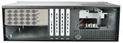
Here's what I want to do. I'm building a dedicated DAW PC and I want to integrate the MIDI interfaces with the case. Here's the basic idea. I know, my photoshop skills are below beginner. That being said, please ignore the MIDI socket in the lower right. It's not supposed to be there. :pinch: The area above the motherboard I/O will be Dremeled out and a piece of aluminum will be pop riveted in place. So I want to mount the MIDI boards inside at the front, then remote the sockets to the rear. Everything isn't exactly to scale, but it should fit per the image. Also, the activity LEDs are going to be mounted to the front, through the front bezel and aptly labeled. For the USB connection, I'm going to leave off the USB-B connector on the GM5 board and connect wire to attach both to one USB header directly on the motherboard. As a side note, I plan on DIYing an audio interface and placing the sockets below the PSU. But for now, I'm just going to use my Delta 1010. This case is 3U, so with the audio interface, it will only take up 4U of space. Should fit perfectly in the rack with the JV-1080s! :D
-
Fantastic! I'll work some mockups and submit them. :D