Antichambre
-
Posts
1,291 -
Joined
-
Last visited
-
Days Won
101
Content Type
Profiles
Forums
Blogs
Gallery
Everything posted by Antichambre
-

Displays not initializing after working for a while
Antichambre replied to EvilEvilEvil's topic in MIDIbox SEQ
I found it, there's isopropyl inside but not pure List of ingredients isopropylalcohol Hydrocarbons, C6-C7, isoalkanes, cyclics, < 5% n-hexane ethanol; ethyl alcohol methylal 1-ethoxypropan-2-ol carbon dioxide 2-ethoxypropan-1-ol methanol -
Displays not initializing after working for a while
Antichambre replied to EvilEvilEvil's topic in MIDIbox SEQ
I know we are on a DIY platform;) But sometimes it is better to invest in tools and consumables than to damage one's own work. Isopropyl will do the work but there is a risk of not stopping there and attacking the varnish and all the plastic components. So go for it with delicacy. Personally I use a French brand that does not melt soldermask, silkscreen or plastic. I'm sure you can find the equivalent near you. Translated name is "low surface tension flux cleaner", exact composition is not specified. Best Bruno -
Displays not initializing after working for a while
Antichambre replied to EvilEvilEvil's topic in MIDIbox SEQ
You call it 3 times!!! maybe "Evil" is in your circuit!!! And we have to call an exorcist now! -
Displays not initializing after working for a while
Antichambre replied to EvilEvilEvil's topic in MIDIbox SEQ
I found it in previous page of topic, but there's too much flux residue on the back of your board to discern something. There's already some suspicious pads like those: Maybe this is just reflect, and it's difficult to see the relief from a top view picture... I suggest you to clean all pads with paste flux and iron, no need to add more solder, then clean the board(good flux remover) take a picture and share with us please. This is the paste flux I use: Best regards Bruno -
Displays not initializing after working for a while
Antichambre replied to EvilEvilEvil's topic in MIDIbox SEQ
I suppose R33 is in the good way too? -
Displays not initializing after working for a while
Antichambre replied to EvilEvilEvil's topic in MIDIbox SEQ
Hello, Maybe you already did it also? But Diagram + multimeter and continuity testing of all the tracks between the STM board and the LCD, Maybe -
Because you already own it... of course ;) I also continue to use it a lot, this board is very small and thin. Best Bruno
-
You're welcome, don't worry! I don't know why you choose to use the lpc17 core? Surely for good reason but if not, have a look to the STM32F4 version, it's the same 32 bits OS, this last CPU is just more powerful, you will find more help and advise about it also. Best
-
Have a look on this post, it can help you too. Best
-
;)
-
I did it, LPCXpresso1769 with CMSIS-DAP is working without any firmware and pinout change! Sure! If you prefer to use the old version you can find it at Lextronic web site, it's a french shop and it remains some stock of the old one. Best Bruno
-
Yeah! It's fine!!! But "Everything" I don't know as you can see I use it in a very minimal configuration ;) I'm sure it's working fine on USB power, I tried a direct EXT 5V power to the Main board, fine too of course! I try it before you explain it in the Wiki and we did the same thing, opening BOOT1 surface jumper, removing OSC2 components and FLG/PA5 jumper to get J16 working. I made another test for J18, with 2 others LPC Cores on the same CAN bus, It's working too ;) You respect the original discovery pinout so... no bad surprise during bootloader and firmware setup. You thought it simple and easy, this goal is clearly achieved! :)
-
Great! Pre-order ? ;) ...Keep me in touch! Best Bruno
-
-
-
From the album: MIDIBox 2069
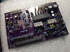
As you can see, there's an error on the 7905 regulator, wrong footprint. This 2 large +/-5V regulators will maybe replaced by smaller package, need to measure current with front panel PCB before deciding... -
MIDIbox 2069 - Proto, testing Analog and Digital Controls
Antichambre posted a gallery image in Members Gallery
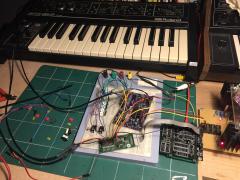
From the album: MIDIBox 2069
The source is a SH9 in amplitude HOLD mode, then continuously generates output. Some trims are used to modulate the CV inputs of the board. The Core is Andy's new one. It controls a PIXI to get configurable CV and Gate outputs. The PIXI is a MAX11300 and is a weapon of choice, have a look if you don't know it... For now, the PIXI drives the "DAC" inputs of the board and the 1V/Oct of the SH9. In software i reused envelope, lfo and routing routines from Nils's synth project, I like his coding style. And created a software module for the PIXI also. -
It should be interesting to get the value you found and which brand you use ;)
-
In theory, Max PCB height should not exceed 112mm. Formula is: 3(RU)*44.45 - 21.35 = 112mm But Eptheca is right, in practice this can vary. See this muff topic. Best
-
Hi, Purple layout and picture are not the same. Purple one is a prototype and not for sale. Picture is the new one, Andy’s Design! Around Waveshare core. Best regards
-
Sometimes after a lot of test and try, I loose connection... Then I restart everything and it connects again. But, "not connected and still load hex" never happens to me. You're welcome. Best regards Bruno
-
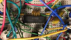
Using TLC59731 ? One RGB Led, This is 3 channels driver. A 32-Bit Data Packet. 8bits command + 3x8bits(RGB). The goal is to relieve the CPU and facilitate the design of the layout. It requires 3 resistances too, but it's only one line between each driver, between each RGB pot. It's 8 pins SOIC package, not too big or too small. In datasheet page 18, it says "There is no limit on how many devices can be cascaded, as long as proper VCC voltage is supplied." Best Bruno
-
About djtechtools, they provide me some samples and the contact for bulk discount...
-
Configuration bits seem fine too. Check the OSC, Q1 on board. Replace it maybe...
-
Yes this option must be checked!