

Antichambre
-
Posts
1,291 -
Joined
-
Last visited
-
Days Won
101
Content Type
Profiles
Forums
Blogs
Gallery
Everything posted by Antichambre
-
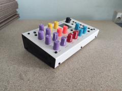
From the album: The HAARP
-
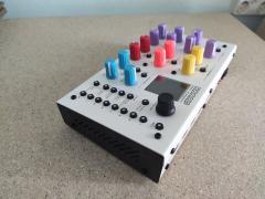
From the album: The HAARP
-
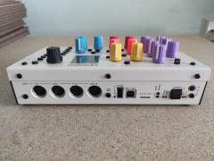
From the album: The HAARP
-
 Put it on J16 which is 3V3, J8/9 is 5V and reserved for SRIO, J19 is 5V too. http://www.ucapps.de/index.html?page=mbhp_sdcard.html
 -
Hi, I risk being scolded because it's not exactly the subject, but it has a relation anyway ;) At the beginning I destroyed a lot of micromatch by wanting to crimp them with a vice or an unsuitable pliers. The official crimping pliers, probably solid gold, is extremely expensive, so I made adapters for the classic 10€ IDC crimping plier. there's a ribbon guide, a male and a female adapter. It works for all type and pin number. result is very clean! Here the drawing, it requires a small CNC to fab it. Peter, Andy, it's a very good idea, It would be perfect if your tester could also make the MIDI cables and Jack 3.5. :) Very good cause it tests continuity and short-cut, Great! Have a good WE! Best regards Bruno
-
Like I said before, it's not something easy. SD Card can be shifted to any predefined SPI port J16(default) J8/9(SRIO) and J19. They are unfortunately not defined over your requested pins. Moving the SPI to your desired pins is something deeper, and the functions defined on this pins will have to be moved somewhere else then move another somewhere else again. It's not in one unique file, it's multiple header files you have to modify in MIOS32. There's no quick answer for your request, it needs study and time. Best regards Bruno
-
Hi, All pin of the STM32F4 are General purpose I/O(GPIO) but they have limited alternative functions. The pins for this SD Card are used for other ports/peripherals. PC10 is used for the onboard DAC(Disco) PC11 is the LCD Read/Write PD2 is the UART5 RX(MIDI) PC12 is the UART5 TX(MIDI) Etc... So you will have to remap more than this pins, cause the functions you remove has to move on an other pins, to get all MIOS32 ports available and avoid conflict. I strongly suggest to follow the regular pinout and add an external SD Card Socket ...Or you can download the datasheet, open a blank excel sheet and start a long adventure... ;) Note: your CPU must be a STM32F407xx for MIOS32 to work properly. Best regards Bruno
-
Older images in the gallery are no longer displayed.
Antichambre replied to mfk's topic in Miscellaneous
Thank you Thorsten, that's great and beautiful! Before I was not able to slide down in my albums, it constantly went back up in the page, like an elastic ;) Now it's fine :) Best regards Bruno -
Too much complicated. All internal clock and PLL settings have to be change etc... Swap the crystal or use a board which directly work with it.
-
Yeah I checked it now, it seems the crystal is a 12MHz on this board, you need a 8MHz to make MIOS32 work on this.
-
DFU is a feature of the MPU not of the board. Most of STM32 provide it. Check AN3156 I use QMK Toolbox, it's made for QMK HID firmware but it works fine for me with DISCO and WAVESHARE. No need to create a DFU file, connect the board in USB and DFU mode(BOOT0 tied to 3.3V) just load the HEX and flash. done.
-
Compare the diagram and if some peripheral don't perturb MIOS32 pinout. Seems compatible to DFU so USB pinout should be good but check. you use the DFU(IUSB) or SWDIO to upload bootloader?
-
Yep! Seems to be that one! lol
-
Hi, It should be a 'Bankstick' issue, the EEPROM(24LC256/512) which are inside your machine. check their connection or replace it. Best regards Bruno
-
Hi, What he wants is to print arrow for example, from the built-in char set. With MIOS function it's very easy, using Char Print and code number. With NG it seems only string are possible. But according to the C ascii table. the 'left arrow' code 0x7e is "~", so using: label="~ %e" works. But for the 'right arrow' the ascii code 0x7f correspond to DEL, which is not usable in a string. Is there a way to print a label using ascii code instead of string in NG? Best regards
-
Moi je ne connaissais même pas cette petite perle kitch à la française! Un papayou de Carlos encore ouai! Mais ça !? Le plus étonnant est que ça ait pu être déterré depuis le Milwaukee. :) Splendide! ...End of Off topic.
-
No don't worry, some of us are in contact with them. Their last facebook post: " We're not dead, just rebuilding. Give us another two weeks or so - a little patience goes a long way. In the meantime: " LOL
-
Direct Memory Access. A feature which permits a peripheral to automatically read/write from/to memory without cpu processing. Something very important for heavy data transfer, for example.
-
It's a lot of work, first a correct Standard Peripheral Library for F7 must be found, on my last research they provided only HAL. According to Thorsten, setting all the DMA is a tricky thing, something I can believe. Best regards
-
Hi Halvor, It's the same on my side. Except that it's not GM5 but HAARP. But peripheral manager is also good, only Mios Studio is wrong. Best regards Bruno
-
Unable to build MIOS on ubuntu
Antichambre replied to zaordsword's topic in MIDIbox Tools & MIOS Studio
Check this refers to the valid repertories. -
I don't understand why but I can't see the pictures. Got "Keine Fotobeschreibung Verfugbar" instead.
-
Statistically you've got a very small percentage of chance that the mixer's pcbs are separated with Controls only pcb. Exception to the cross-fader which is more often separated to be easily replaced, and usually controls some VCA. All others mechanical controls are generally directly soldered on the active analog board. Like Peter said you will have to sacrifice some of the audio mixer functions for sure, but can be done without definitively destroy the traces and pcbs. With access to the service manual, it's possible to remove the parts(resistors, caps, ICs, etc...) connected to each mechanical controls(pots, faders, buttons) and indicators(Leds, VU, etc..). Next is to find the good candidate... Something like that for me https://www.thomann.de/fr/behringer_dx_626.htm?ref=intl&shp=eyJjb3VudHJ5IjoiZnIiLCJjdXJyZW5jeSI6IjIiLCJsYW5ndWFnZSI6ImZyIn0%3D Very cheap one, 99 € , service manual Then: - Separate the controls you need by removing connected parts and use AIN/DIN. - By removing IC13 you can take control to Leds, VU, digits, using a DOUT and the existing flip-flops which will hold the matriced datas. - You can disable or bypass the useless analog stages using wire and audio coupling caps pads, then keep a minimal audio functions and controls for monitoring/cue outputs. - With a AOUT or some CV Inputs, you can reuse the 4 internals VCA, 4 inputs + main/booth stages, then get 4 controlled/trimmed channels with mixed/trimmed outputs options. - You can reuse the internal 5v and embed the MIDIbox platforms and modules. Add USB/MIDI connectors on a separated back plate with 2 screws, that can hide a potential ugly cutout too. First to do is to print the schematics, get coloured pens and hack this behringer stuff on paper ;) Best regards Bruno
-
Another interesting idea would be to synchronize the fx loop as the mutes can be. But more precisely. With a variable rate from the loop length(steps) to the maximum number of steps in the sequence. And the possibility of synchronizing the entry and exit points independently(enabled/disabled). To be able to play with this effect and to always start or/and resume at the right time. Using 2 new parameters: In and Out rates, value range from Off,1, 2...256. With In limited in software by the loop length and Out by the track length. e.g. Here Loop In is applied when Loop is activated(no sync) and resumed in sync to the measure(16 Steps) just after the Loop is deactivated. Then the Measure restart correctly. // layout: // 00000000001111111111222222222233333333330000000000111111111122222222223333333333 // 01234567890123456789012345678901234567890123456789012345678901234567890123456789 // <--------------------------------------><--------------------------------------> // Global Loop Mode Offset Steps Loop Sync In Sync Out // All Tracks/Step View 15 2 on Off 16 Best regards Bruno
-
It's essential for me too. But we will let Thorsten decide and maybe he has a better way than me to get the same result, he knows this firmware by heart much better than me ;)
