gomiboy99
-
Posts
192 -
Joined
-
Last visited
Content Type
Profiles
Forums
Blogs
Gallery
Everything posted by gomiboy99
-
If you want to modify the clock box, my visual metronome project was based on it, it has been a while since I looked at it but think there was some code for using the eeprom. Hopefully it will provide a few pointers.
-
That port should be connected to SC on J19. Check you have soldered the joint on J19 correctly. It seems unlikely that the track is missing as my board has continuity between J19 and PB6. I assume you have a board from SmashTV.
-
Hi All, I have a problem with my SEQV4 not communicating with an AOUT_NG. The AOUT works in my CV V1 (PIC core). The AOUT works with an LPC core running the latest SEQV4 firmware. I used the cables from my SEQ to run the test, so the cables are fine. The J19 jumper is set for 5V and the 1K SIL resistor is in place and the right way around. I have also checked the core board for shorts and disconnections, all is as it should be. I ran the testaoutpin test with these results: CS 0 voltage = 0.09 CS 1 voltage = 3.91 SI 0 voltage = 0.09 SI 1 voltage = 3.87 SC 0 voltage = 0.10 SC 1 voltage = 4.99 HIGHER than expected on this pin. I suspect I may have damaged the SC port on the STM32. Before I order a new MCU and tear the SEQ apart, is there an easy way around this problem? Thanks in advance. Tim.
-
I have a SEQv4 with 7 outs, I used the BLM connector as normal MIDI and used an IIC module (you can get kits from http://www.midibox-shop.com/buy.html). The additional 4 ports are USB but I don't think these are designed to be connected to synths,they are used to connect to a PC/DAW.
-
I use a Microchip ICD2, you can get cheap clones of this on EBAY, just search for ICD2. That should do the job nicely.
-
I have fixed a couple of bugs that I discovered today. The new files are available from the wiki here.
-
-
-
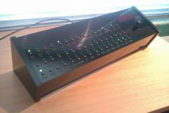
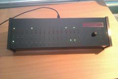
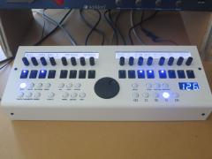
From the album: Gomiboy99's Midibox album
Details in the wiki. http://www.midibox.org/dokuwiki/doku.php?id=mb_visual_metronome&#master_unit_design -
After a year of other distractions, I have finally updated the VM project to version 0_2. Changelog: updated menu to add store, recall and format functions for eeprom added eeprom routines to store 32 presets DIN pin assignments corrected to conform with documentation I discovered a small error in main.c with the set-up of the LEDs on power-up. This is now corrected. Please note that pre-compiled hex files are in the downloadable zip file. I have tested the PIC18F4685 version but the PIC18F452 is untested as I don't have a spare chip at the moment. The WIKI has links to the updated files.
-
 OK, found the answer, it's in the manual.
 -
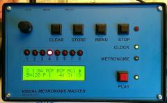
Nice work! I like the minimal design of the control surface. I already have a seqv4 with the wilba panel but want to build a more compact and simple version for my modular synth project. How do you select different tracks and parameter layer with the single buttons on the left side?
-
Hi, I think I could use one of these too, if there is one available. Thanks Tim.
-
Many thanks
-
Hi TK, thanks for the update, I really like the new file browser. Is it possible to add the multi bank to the Blofeld librarian? I have been using this a lot since I got the keyboard version. Happy New Year Tim.
-
Control surface PCB for 16 encoders/LEDrings Bulk Order
gomiboy99 replied to Fairlightiii's topic in Bulk Orders
Email sent. -
Control surface PCB for 16 encoders/LEDrings Bulk Order
gomiboy99 replied to Fairlightiii's topic in Bulk Orders
4 more PCBs added to the wiki page. Nice design. -
Midi or USB connection to the core? Check MIDI IN and OUT are the correct way around. Have you separated the LPC-LINK board or cut the tracks if it is still attached? If you are using USB, try a system reboot and then connect the core before starting MIOS Studio.
-
Lee, thanks for a great project, just finished mine. I am sure it will be most useful. To anyone else considering building one, be aware that the TDA1543A is different to the TDA1543. I used a TDA1543A, wrong! It works great now I have a TDA1543. Tim.
-
The board is available here http://www.midibox-shop.com/buy_lvo.html
-
It is always the simple things that cause the most trouble, great that you found the problem. It was just an idea, I have built your circuit on a breadboard and it works fine. The only difference is that I used a 74LS14 as this was all I have to hand. The best thing is to use your circuit and see if problems occur. If it works fine then use it. Tim..
-
The simple answer is that Midi uses a 20mA current loop to send and receive data. You always need an opto coupler on a Midi in. I am not sure that the 74ac14 is the best thing to use, it is a schmitt trigger type, midi really needs an open collector type. I have built quite a few thru boxes using a very similar schematic and usually use either a 7404 or 7407 (depending on the type of opto coupler). In your design, the 6n136 is an inverting type so I suggest you try a 74ac04. Hope that helps. Tim. Ps here is a link to my design
-
Let me know if you build one.
-
couldn't commit memory for cygwin heap, Win32 error 487
gomiboy99 replied to gomiboy99's topic in MIOS programming (C)
Thank you Thorsten, it is all clear now, my small misunderstanding caused a lot of problems. Tim.. -
couldn't commit memory for cygwin heap, Win32 error 487
gomiboy99 replied to gomiboy99's topic in MIOS programming (C)
Hi Thorsten, I seem to have missed or misunderstood a vital piece of information when setting things up. Is there a guide on what to do or not to do with files in the repository? As far as my project is concerned, I could remove everything I have committed and start again. Rev 1038 is OK. If you have the time then you could sort out my mess, if you want to, I guess I would see what is different. If the release code does not go in the svn repository, where does it go? Sorry to ask but I have not found an answer yet. Tim.. -
couldn't commit memory for cygwin heap, Win32 error 487
gomiboy99 replied to gomiboy99's topic in MIOS programming (C)
Solved. Deleted and downloaded rev 1038. There seems to be something wrong with 1039, I changed a couple of things in my project and this seems to have caused the problem. I am getting a warning "processor mismatch in pic18f4685.o", not sure how serious this but I may have the wrong linker or library file. Tim.