

TAG
-
Posts
27 -
Joined
-
Last visited
-
Days Won
1
Content Type
Profiles
Forums
Blogs
Gallery
Posts posted by TAG
-
-
Yes, I have forked the code and plan to start digging in. What I was hoping to find out was a kind of big picture of what is missing. It looked to me like there was quite a bit there already and it wasn't obvious what the missing pieces were.
-
The reason I think that an updated version of the SID project makes sense isn't for performance, but rather cost and lowering the bar for the community to add new features. The PIC is expensive and people are less likely to tinker with assembly. Also the recent developments in reproducing SIDs in FPGA make an updated STM32 version more enticing. Would it be possible to get some information regarding what would need to be done in order to finish what TK started? I am interested in helping move the project forward.
-
I saw the conversation about the FPGASID project and I'd thought I'd share some work I have been doing regarding SID implementation in FPGA as well.
I purchased a Papilio Pro (http://papilio.cc/index.php?n=Papilio.PapilioPro) board as part of the retrocade synth (http://retrocade.gadgetfactory.net/) a while ago and recently decided to try and find out how many SIDs I could fit into the board if I took everything else out. I ended up with 4 SIDs plus the associated shift registers that I am able to connect right up to my MIDIBox MB6582. I can even drive both real SIDs and the FPGA versions from the same signals from the MIDIBox in order to do A/B comparisons.
I am working on designing an interface board to connect the midibox to the papillio pro, it isn't finished but if anyone is interested it is here: https://upverter.com/LVL1Soundbuilders/32fbede244e1a406/Papillio-Pro-to-Midibox-SID-Interface-PCB/
The papilio pro is open source, the board I am working on is open and I'd be glad to share my file of the 4 sid implementation. I'll post a link once I decide on the best place to put it.
-
Found the answer for the FM here:
-
They are custom caps milled from acrylic sheet.
-
I finished my project a couple years ago but never posted pics, you can find them here: http://wiki.lvl1.org/Isomorphic_Keyboard
-
 2
2
-
-
What is the status of the SID and FM projects in the MIOS32 SVN repo? Are they functional?
-
Every time I tried to upload the application I got the same error, and the application ran with what I assume was a blank patch (the displayed patch name was >>>>>>>>>>>>>>>>>>>> or something like that).
I swapped the 452 out for a 4685 and was able to upload the 4685 application 100% and the application ran with the Fender Rhodes patch. I will probably try completely erasing the 452 and trying again just out of curiosity.
-
I am using a 452 with the 452 firmware. Mios studio shows 20736 bytes of flash and 256 bytes of EEPROM, is the 256 bytes of EEPROM the single default patch? It seems that what is happening is that I have the application with a blank patch. I got it to work by sending a patch with the SYSEX tool. It seems to be working fine now but I'm not sure why the application download in MIOS Studio isn't able to complete 100%.
-
It gets to 98% then displays "Upload aborted due to error #4: Write failed (verify error or invalid address)"
-
Is there EEPROM within the 452? Is is possible that the flash is being programmed properly but not the internal EEPROM?
-
I have a basic MBFM setup: Ctrlr, the MBHP_OPL3 module and the MBHP_CORE.
My understanding was that once I started the MBHP_CORE with the MBFM application I would be able to play an e-piano sound with no control surface, but I am not able to get any output. I have loaded the test tone application and that works fine.
After loading the test tone, when I went to reload the MBFM application in the core I got an error message in Mios studio during the download, but the MBFM application was still able to start up and run. Does Mios studio try to program a bankstick at the same time as the application? I don't yet have a bankstick in my setup.
Thanks
-
Thanks for all the help, here is a link to my working project on the make blog:
http://blog.makezine.com/archive/2011/03/diy-isomorphic-keyboard.html
-
The switches on the bottom PCB are: Panasonic EVQ-Q2B03W
They have an activation force of 50gF. Unless you are intentionally feeling for it, you don't notice the 2nd switch at all.
-
Check out my prototype on the make blog:
http://blog.makezine.com/archive/2011/03/diy-isomorphic-keyboard.html
-
I see now: MIOS32_SPI_PRESCALER
-
I have my 24 x 16 matrix working. It works pretty well as is, but I want to experiment with scanning faster. I have been poking around in the ST reference manual and the code trying to understand how to change the SPI clock. It looks like I need to change the APB low-speed prescaler (APB1) is this correct? Will other peripherals used by midibox be effected by changing this prescaler? Where is this set in the code?
Thanks,
TIm
-
If so, check out the Louisville Soundbuilders:
Louisville Soundbuilders is an audio electronics interest group that meets at the LVL1 Hackerspace in Louisville, KY. We meet every other Monday at 8 PM. Now we have a web forum: http://soundbuilders.lvl1.org
-
I ended up finding a tactile switch with 50gF activation force, it is low enough that you barely notice when the 2nd switch is being pressed.
-
Thorsten commented that the 16 x 16 matrix loaded the CPU by ~40% so I am assuming a 24 x 16 matrix would load the CPU by ~60%. I have a 32 bit core on order so I am going to give it a try when it comes in. It might not be necessary to change the SPI clock, but that will offer another lever to pull if I have issues with speed.
-
I see that the limit is 16 shift registers on both input and output due to signal integrity issues, but what I am suggesting would only be 3 shift registers on one chain (either input or output) and 2 on the other. Well below the limit of 16 shift registers.
-
Would it be possible to modify this project to add either another DIN or DOUT in order to achieve a 24 X 16 scan matrix? I am working on a 192 key velocity sensitive keyboard (axis-64 clone).
Is it just a matter of changing these:
// scan 16 rows
#define MATRIX_NUM_ROWS 16
// maximum number of supported keys (rowsxcolumns = 16*16)
#define KEYBOARD_NUM_PINS (16*16)
Thanks,
Tim
-
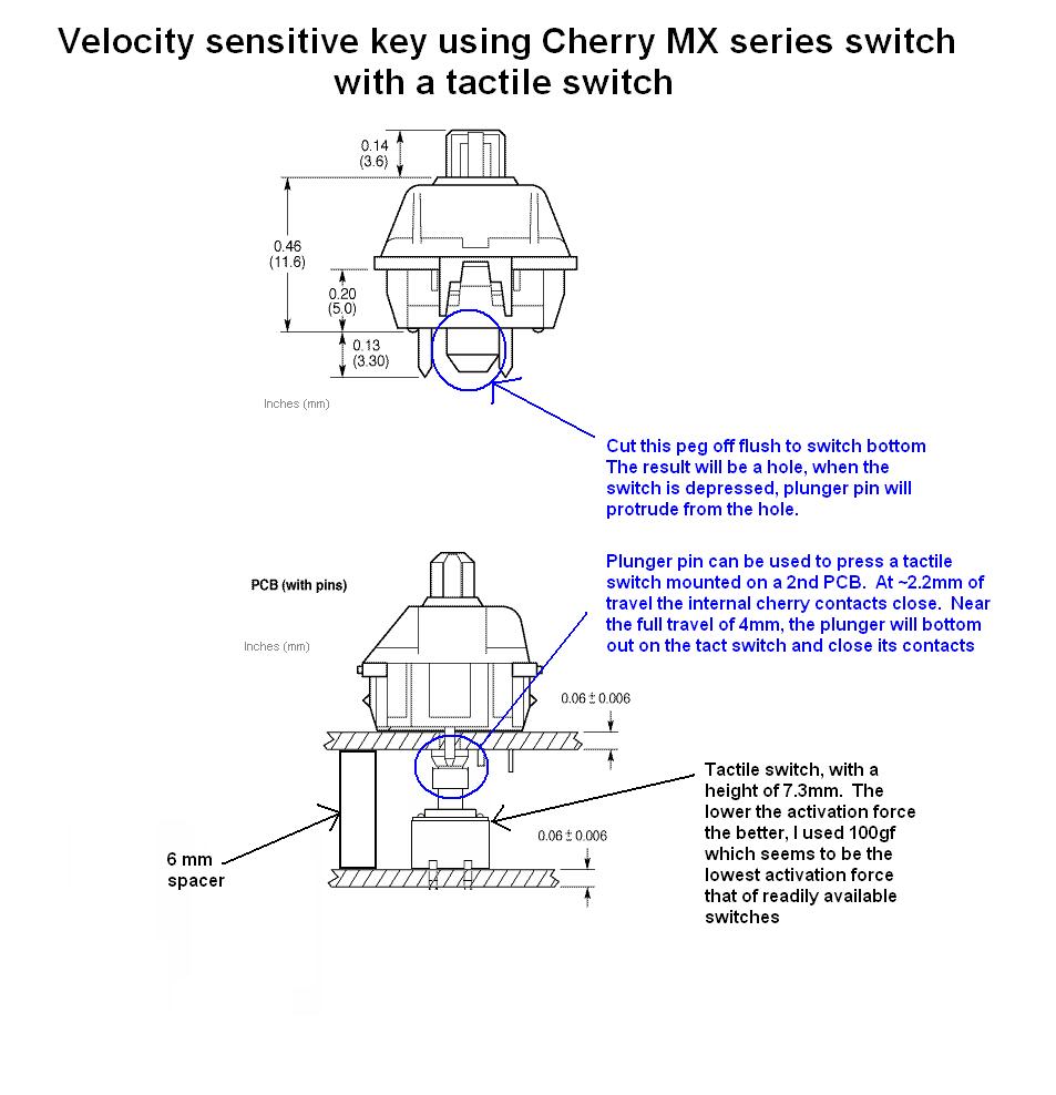
I am working on making a copy of the axis-64. It is based on cherry MX switches, I am using a different method to achieve the velocity sensing. See the attached diagram:
So far I have used din_velocity_unmuxed_v1c.zip for software and have achieved good results, but this project is limited to 64 keys. I have seen the fast scan project for the 32 bit core, but even that project is limited to 128 keys. Does anyone have ideas for achieving 192 keys (384 inputs) or is this not feasible for a single core?
-
Does anyone know if the Bourns PSM Series Motorized Slide Potentiometers can be used for midibox LC?
Details here:
MIOS32 SID and FM applications
in MIOS programming (C)
Posted
Thanks TK, this is exactly the kind of information I was looling for!
Hyperr, i did consider attempting to synthesize the pic in the fpga, but i dont think it would be worth it considering the resources it would use that could go to more SIDs, and also I havent found a good candidate for a core that would be a drop in anyway.