

daemonik
-
Posts
48 -
Joined
-
Last visited
Content Type
Profiles
Forums
Blogs
Gallery
Everything posted by daemonik
-
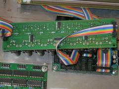
From the album: daemonik
custom Encoder and Step-Button PCB, rear-side -
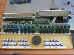
From the album: daemonik
Encoders and Step-Buttons on custom PCB, + MEC Buttons on Veroboard -
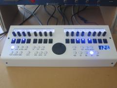 My beloved SEQ V4 The UI is reduced for my needs - working with it is very intuitiv always loved this Step-Buttons blue LED's are indeed very bright (used 3k) but the photo over-accentuates it case was ordered from Schaeffer - great Quality!!! This Sequencer is AMAZING
 -
Okay...Thanks I have to admit, that I'm far from knowing all the functions of the SEQ V4 that is because it is simply so unbelievable AWESOME :hyper: ...and I feel like a kiddy turning notes on and off :hyper: however the mentioned redundancy makes sense, to me at least: While in Live mode I've finished with programming Sequences and want to play with 'em But with this option it's possible to quickly play notes from a keyboard during programming of a sequence... Maybe I still didn't understand live mode completely.... ? I took some time last evening in learning all the functions but stuck in the track-direction-menu-page twiddling around till late in the night :sleep: FANTASTIC...... Since this weekend spring time and barbecue season will finally start... I guess it's time for spending a beer or two to you TK!
-
I much appreciate the MidiRouter "Track" Destination introduced in V4.071 however I slightly changed the code for my purpose so that the router sends incoming midi to the port and channel of the currently selected track: I didn't investigate the code very deeply, and thus I have no clue of any possible conflicts nor reliability... but up till now it works for me!!! I'm no programmer, so I'm far from adding this as additional option instead of replacing. Maybe you programming-goddess can add this option in the future... btw: with the above code, the compiler gives a warning... do I have to declare the Type of SEQ_UI_VisibleTrackGet() in SEQ_CC_Get(........)?
-
I'm also not much convinced about using a switching psu! particularly for the analog path! Still I gave it a try... with the option to replace it with a Transformer - Vreg(+/-) and switching 5V regulator. But at the moment I'm fine and can't recognise any noise! What about using a Vreg in series with the swichting psu? does the switching noise propagate thru it? since I only use 6582 the whole analog path is essentially fed by a 7809. further an opamp mixer shall be included which will be fed by +/-9V from Vregs. Then what about the AOUT-NG Module? is it wise to feed it with +/-12V from the switching psu? what do I have to expect? my Midibox CV V1 is also fed with a cheap 15V switching psu at the moment (yes unipolar) - and up to now I'm quite fine with it Thanks for the Power One recomendation :smile: hopefully soon I will start with a modular.... but probably i will go with an adjustable transformer-Vreg psu
-
If you don't need the -12V you don't have to connect it. I'll use it for the CV-OUT Option (AOUT-NG Modul) and further I want to add an Opamp-Mixer for the 4 SID Modules. If all this doesn't mean anything to you - don't worry about it! you could still connect the -12V later if needed. C2 and C4 are 330nF = 0.33uF not 330uF - you can use standard ceramic or film capacitors e.g.: http://it.mouser.com/ProductDetail/TDK/FK24X7R1H334K/?qs=sGAEpiMZZMuMW9TJLBQkXjcE1SaKS%2f8mCuct0Dgx3Ik%3d capacity of C4 is not that critically, anything between 100nF and 1000nF will work If you don't use 9V: 7809, C11 and C12 are obsolet
-
I've done it that way: Using the 7pin Connector and a MeanWell RPT-60B However I only use 6582 (9V) and don't need to connect the 12V path on the board (beside feeding the 7809) For the 12V path you could solder a wire from J25 upper pin (beside the rectifier) to J4 lowest pin You could leave the 7809 out if you don't need 9V I highly recomend to solder the capacitors C1...C4 !!!!! and C11...C12 for the 9V path if used
-
Finished my external PSU based on the Mean Well RPT-60B last week and can't recognize any additional PSU introduced noize. 12V > [2200uF and 330nF] > 7809 > [10uF and 100nF] 9V > 6x6582 5V > [2200uF and 330nF] > 6x6582 and 4xPIC I'll go on and add an active Mixer (OpAmp) stage soon - using 12V/-12V supplies reduced to 9V/-9V by 7809/7909
-
It's spare! like noted in the document you reffering to! so... no need to connect it anywhere :thumbsup: If you'r using the Quad IIC Midi Modul from smashTV then also check this Schematic: http://www.midibox-shop.com/images/quad_IIcMIDI_schem.pdf cheers, Nick Ahhhhhhhhh... stupid me!!!! I've installed a 7pin instead of 8pin!!! argghhhhhh!!!!!
-
Hmm! Ich geb mal meinen Senf dazu.. ohne Gewähr! -VST ist eine Schnittstelle zwischen DAW und Plugin's -Plugins geben keine Daten direkt an irgenwelche Treiber weiter -Paramter werden über die VST-Schnittstelle registriert, sind aber teilweise auch via Midi ansprechbar (= Midi-Teil der Schnittstelle) -Plugins senden typischerweise (Ausnahmen wahrscheinlich) keine Mididaten an die DAW zurück Dies sind mehr Annahmen als Facts meinerseits (habe schon seit einiger Zeit nicht mehr mit VSTs gearbeitet). Das von dir gewünscht Feature hat meines Erachtens bisher gerade mal Novation zustande gebracht. Da werden die VST Plugins in ein Novation VST-Plugin Mantel gepackt, welcher dann direkt mit der entsprechenden Hardware kommuniziert. Brauchte aber einige Versionen bis alles "reibungslos" funktionierte. Ich lass mich natürlich gerne korrigieren.
-
Congrats! :thumbsup: I love the MIDIBOX CV too, considering building another one/two... I also tried to power it with a MFOS wallwart bi-polar power supply but had considerable errors with it! The device didn't power up properly every while and then. That happend in general when turning on shortly (<10sec) after turning the suppy off. It showed, that the positive supply (core + aout_ng) had a slightly negative voltage. I've changed to a unipolar supply since I didn't need bipolar for my current setup... but with a DIY modular as future-project I'll get back to this issue. No problems with yout power supply?
-
ahh... nice! thank you Thorsten but I doubt that I can apply such long Sysex-Strings to buttons on my controller-Keyboard. My idea was that I can change the input (MIDI-Keybord) to output (all SEQ-Outputs) routing by one fingertip on the keyboard.... For the moment I'm fine with changing the routing in the menu! But I will definitely keep an eye on that... btw: i guess 0x00 0x00 are manufacturer- and device-ID? Does the second corespond to the MIOS-Core-ID? or how can i ensure only the intended device reads a SYSEX-DUMP? I've built a Midi_Processor (CC to SYSEX conversion for Waldorf-Microwave1) years ago based on the 'MIDIfilter/processor'. the matching of CC# and SYSEX-Parameters can be changed with SYSEX-DUMPS to the Processor. The Device is also adressed with 0x00 0x00, but I guess this can cause problems when using other gear with no specific ID's cheers, Nick
-
Yes you are right! but... that way I can only drive 16 midi channels in total from SEQ and keyboard (when setting up nodes for USB-MIDI to midi-out and midi-in to midi-out in parallel its reduced to 8) However I need: 4 for NordModular 4 for NordModular G2 4 for MB6582 4 for MIDIBOX CV (4 analog Synths) also ther is a x0xb0x / a Microwave1 / a Machinedrum / ... Well... definitely... awesome... I'm blown by it :frantics: and I guess I should first start with ENJOYING and think about the possibilities/options later at least it also doesn't need a lot of button hits to chang routing within the menu
-
sooooooooon I will have finished my SEQ V4... everything is working now, last thing to do is the enclosure Now as it comes to an end, I'm thinking about how to integrate this AWESOME piece of equipment into my setup.... I plan to use the SEQ V4 as MIDI 'control center': all synths are connected in (4) chains to the sequencer a keyboard controller is hooked to the midi-in of the sequencer MIDI-ROUTER is used to connect keyboard/USB-MIDI with synth chains Within the MIDI-ROUTER: 4 nodes are used to connect USB-MIDI (1-4) to 4 synth chains (IIC-Midi connectors) 1 node shall be used to connect the keyboard (MIDI-In 1/2) to the 4 synth chains (IIC-Midi connectors) since I want to be able to switch the output (chain 1..4) that is hooked to the keyboard input, this configuration needs the ability to modify the MIDI-ROUTER settings from external. By reading the changelog I found that this might be possible by using MIOS terminal commands. But I rather want to be able to modify it directly from my keyboard. 2 possibilities come to my mind: [*]change the settings of a node (the keyboard to synth-chains node) with a sysex-string (thus i can assigne appropriate sysex-strings to 4 buttons on my controller-keyboard) [*]introduce presets for the router, which can be switched from external First option is prefered. Seems to be more easy. All I had to do is to add a function in seq_midi_sysex.c which calls a node-setting-function using the parameters received in a sysex-string. Right? Can u follow my explanations? Better ideas? Workaround? Did I miss something? How do you do it? controlling a synth with the SEQ and a keyboard in parallel without booting the PC? Any ideas/recommendations/warnings/hints welcome! btw. YES i thought about using external Midi-Mergers (it's not an option - I DO WANT to implement it in the code :drool: )
-
Huhh.. I was wrong: It's SR-1 PIN-7 not PIN-0 Here's another photo of the Encoder/GP-Button Module I made It was my first time with SMD... and soldering is not very clean
-
Almost finished my SEQ_V4 :frantics: :frantics: :frantics: :frantics: :frantics: have to go ahead with the enclosure! However, the very first LED (step9 / SR-1 PIN-0) in the chain is flickering in play mode. Can't say if it's an erratic flickering or following a pattern Normally this led is the BEAT-Indicator, but I changed the assignement of that led and set all non-used led's to SR-0 LED works correct when SEQ is stopped - only flickering when playing any idea? Just currious, I can easily change the order of SR's and leave SR-1 PIN-0 unconnected cheers, Nick
-
Only had a brief look... but encoder pinning is opposite the standard MIOS pinning: PinA goes to 'higher numbered DIN pin' PinB goes to 'lower numbered DIN pin' see Wiki I've designed some SEQ V4 boards, made exactly the same mistake and ended up in editing the code...
-
Thank you Thorsten... of course I won't inverse the direction twice :rolleyes: was it intended to connect pinA to D1 and pinB to D0? intuitively I' ve designed the board the opposite ... which turned out to be wrong. However this forced me to have a closer look to the code finally ... and I'm going the learn C and programming MIOS-Apps for shure BTW. concerning the encoders ALPS STEC11B from Reichelt which work best in DETENTED3 mode: The encoders work similar to DETENTED2 (one detent position per cycle) BUT: detent positions are exactly at the rising/falling edge of terminal B (according to the spec-sheet:SPEC-SHEET ). this may explain the wobbly behaviour of the encoders in most modes (at least when turning cw, where inc is detected at the rise of terminal B). However, what's different in mode DETENTED3 then? cheers, Nick
-
The step encoders of my SEQ-V4 increment by turning ccw and decrement by turning cw :frantics: So I want to change the direction of my encoders within the code of SEQ V4. But I feel unsure what code to add and where. My guess (as C and MIOS rookie) is following code either in /core/seq_ui within the Encoder handler: ///////////////////////////////////////////////////////////////////////////// // Encoder handler ///////////////////////////////////////////////////////////////////////////// s32 SEQ_UI_Encoder_Handler(u32 encoder, s32 incrementer) { incrementer = 0-incrementer or in /core/app: void APP_ENC_NotifyChange(u32 encoder, s32 incrementer) { incrementer = 0-incrementer doesn't make any big difference (as long as Idont use debug mode), right? thanks for your inputs! btw. change of the pinning hardwarewise is not really an option. I've (also for the first time) designed my own boards for Step-encoders, GP-buttons and GP-LED's. Accidentaly I mixed up the pinning of the encoders. The boards use smd parts :afro: and soldering wires between encoders and smd 74hc165 just is too fiddly...
-
Ich benutze ebenfalls ALPS Stec12e Encoder gekauft bei Reichelt. Meine Erfahrung ist auch, dass der Modus DETENTED3 am besten funktioniert bei denen. In den Modi 1 und 2 passieren oft einfache Parameter-Sprünge beim blossen Berühren der Encoder, resp. dann zusätzliche Sprünge nach dem Drehe am Encoder (in die eine oder andere Richtung). DETENTED3 funktioniert aber einwandfrei. Die Encoder sind im Übrigen korrekt angeschlossen :thumbsup:
-
HI I want to build a this little helper Midifilter to convert Midi CC messages to Sysex-strings for the Waldorf Microwave1. I stumbled on the IFSET and IFCLR macros in macros.h which are not read correctly by GPASM. These macros have been changed to a new version by thorsten on most apps but not for the Midifilter. As I understand, only thing to do is to replace the macros by the new ones and change the sourcecode for the new macros? But why do BTFSC and BTFSS need 3 arguments in these macros? (reg= Register-Name/Number; bit=Bit-Name/Number; but what's the argument reg_a????) cheers, Nick
-
Thanks for your helpful explanations. Indeed I would have missed about the power ratings (btw: (12V-3.5V)/0.12A = 71Ohm; and P= ~1Watt). For now I will go for the Resistor and Pot. if some illumination jitter appears I can switch to the Transistor based current-source Can you please explain me the purpose of the 10k Resistor between 5V and the BC337's collector in the core32 schematic?? Is it really needed? Dam...indeed VFDs do look old-skool... would make a great design accompanying retro synths however my first MB SEQ will sit in front of a NordModular, a NordModular G2 and a Blofeld... so no need for style yet
-
I've got 2 of these LCDs: digikey optrex (datasheets at digikey!) black dot's and white LED backlight My general problem is, they are not equally illuminated and have unequal contrast! thus I probably have to use two separate illumination/contrast control circuits. As for contrast, this is not difficult... but I have some uncertainties with illumination: 1. I'm no expert but I guess I could also drive the backlight LED's with 12V??? 12V are used since I want to connect an AOUT_NG-Module and also need 12V Gate Outputs (Roland System100 and hopefully some other in the future). furthermore, 12V for LED backlight would be much appreciated by the 7805 which gets really hot (~90°C at 250mA backlight current [spec. stats a max current of 125mA for each modules backlight]) 2. could I use just a resistor and a pot in serial instead of the constant current source for each module? or would this lead to unstable illumination? I'm using a 12V 1.5A switched PSU. any help is much appreciated!!! and merry x-mas to all
-
Hi I'm prepared to build a SEQ V4 which makes me very excited.... Core Module, DIN and DOUT Modules, Knobs, Encoders, PS ... almost everything is ready!!!!!!!!!!!!!!! There is just ONE uncertainty here after reading back and forth trough device descriptions, forum and MBSEQ_HW.V4: How to handle the LED's of GP Buttons and Step-Indicator??? I will use these GP (step) buttons: Buttons Either I will use dual color LED installed to the buttons or standard LED to the buttons plus a separate Line of 16 LED's for step indication. The concepts are some what different. For the first unmuted steps LED have to be de-illuminated when step-indicator comes to respective step. Whilst for the second option with a separate line this is not desired! My quenstions are: Are both options possible? and what are the respective configurations I have to make in MBSEQ_HW.V4? can I use this section for either option? (line 47) # DOUTs for Dual Color option: GP_DOUT_L2_SR 0 GP_DOUT_R2_SR 0 or do I have make my configurations within here: (line 61) ################################################## # Optional BLM Matrix ################################################## isn't the later section intended for the usage of separate dual color LED's for each track of a track-group? I only want the respective track highlighted by the track selection buttons to be indicated by the LED's regards, Nick
