

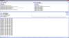
CSC
-
Posts
72 -
Joined
-
Last visited
-
Days Won
1
Content Type
Profiles
Forums
Blogs
Gallery
Posts posted by CSC
-
-
i become a f... o.. with this. :sick:
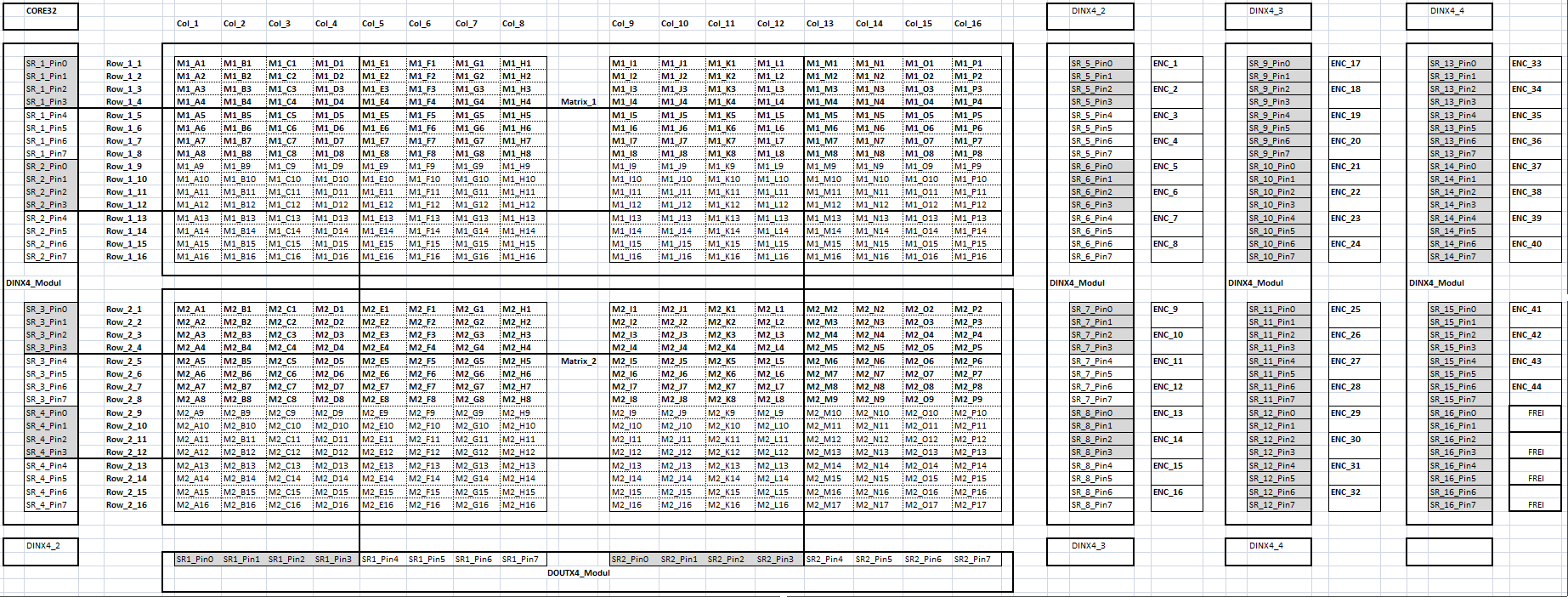
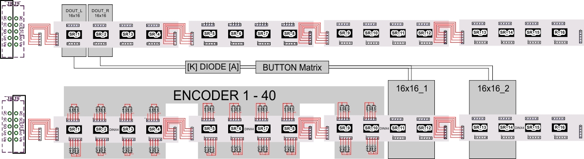
Now i build in, 4 Encoder more. So, i have the Shift Register 1-12 (DINX4_1 - DINX4_3) complete connected with Encoder.
I changed any point in the Program...
#define NUM_ENCODERS 48
#define NUM_MATRICES 2
#define FIRST_ENC_DIN_SR 1
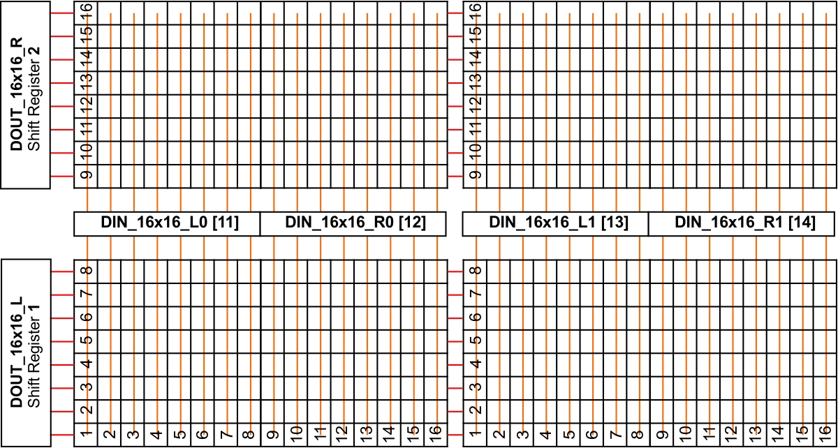
// DINs of first 16x16 matrix (counted from 1)
#define DIN_16x16_L0 13
#define DIN_16x16_R0 14
// DINs of second 16x16 matrix (counted from 1)
#define DIN_16x16_L1 15
#define DIN_16x16_R1 16
// DOUTs of both matrices
#define DOUT_16x16_L 1
#define DOUT_16x16_R 2
Now the new last 4 Encoders doesn´t work but the 4 Encoder that i connected before... :question:
What a hell!?
and Now the Matrices doesn´t work well.
i don´t give up!! :hairy:
I will try to change the parameters of the matrices and take look a the encoder connections, and send after a new try some feedback.....
-
Can someone help ??
The Program already exists in the Repository of Mios32/trunk/apps/quickies/csc , but it has to be updated...
Greets CSC
-
I need a new program for my Midi Project CSC....
a preprogrammed sample is already in the repository in the apps/quickies/csc folder.
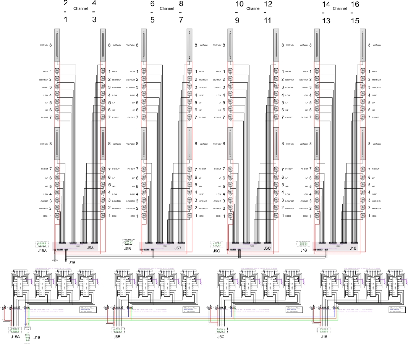
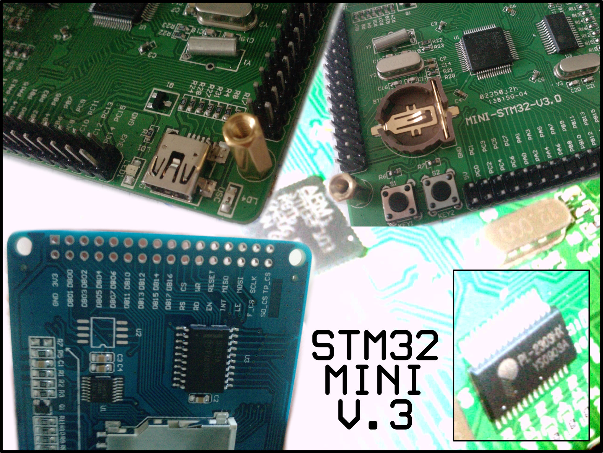
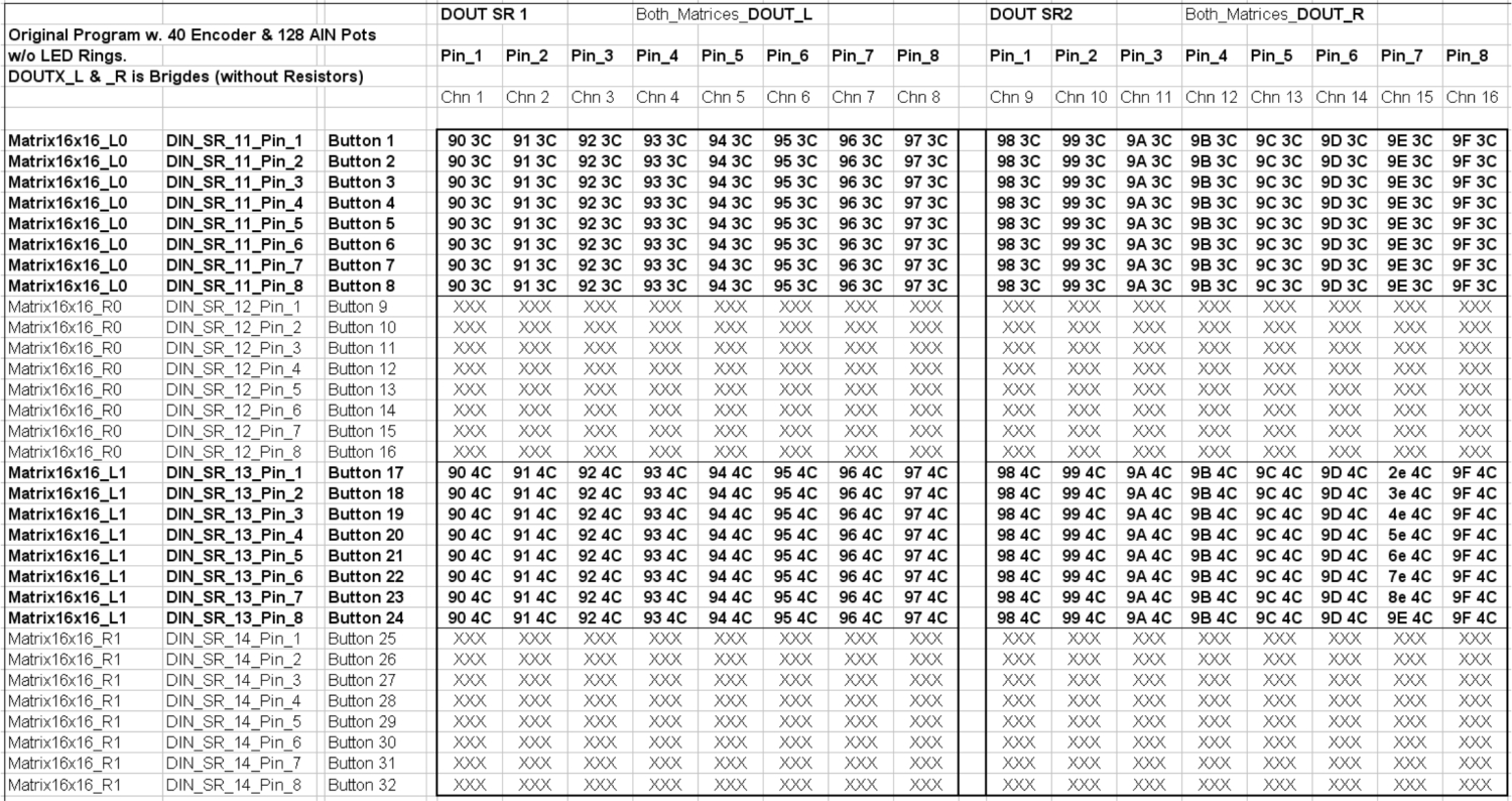
The Based Version was created with 40 Enocders, 128 Pots, an 2 16x16 Matrices at 4x AINX4 Modules, 4x DINX4 Modules, 1x DOUTX4 Module at a Core32 Board over USB to the XP PC.
The new Version has 4 Encoders more.
I have also tried to change the details in the program, but it doesn´t work.
Can someone write a new program or an update for this Controller?
It worked fine with 40 Enoder and all other parts till i build in the 4 Encoders in.
Thanks a lot for help.
Greets Chris
-
Background from this topic was a small answer for members who want to get some informations about the cable length, if they only find the answer,
that the cable length... has to be short as possible.
and for sure, this not only the point for the maximum cable length factor but better than searching hours in the Web for a little answer...
In this case, for a better understanding why i typed these in, was...
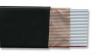
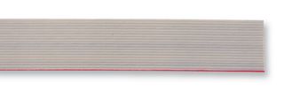
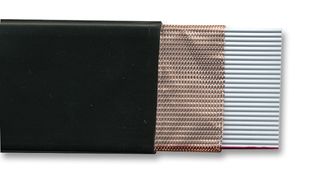
Best cable i could chance, for a better connection, was the
3M - 3302-40 - RIBBON CABLE, 40WAY, 30.5M (with PVC Polyvinyl chloride Jacket) (non drilled) (Farnell Order Code: 8608636)
for the
3M - 2010-40 - RIBBON CABLE, 40WAY, 30.5M (with Polyolefin Jacket) (drilled) (Farnell Order Code: 4140679)
with same length.
I think, the Insolation of the cable, was the point.
I had to connect Encoder to the DIN Boards with a minimum length between 25-30 cm.
The signal with the standard "tinned" cable was so terrible, and bad for sure when i touched it.
The notes are spinning around......
I soldered the Encoder with the "Rainbow Drilled" Cable, and the same length and finish.
Good events and a stable connection, with the same length.
There was not only the cable length the problem, only the Material..
"but it had to do with the length! :whistle: "
For the Board connections, i found these insolated ribbon cable.
3M - 3517-40 - RIBBON CABLE, 40WAY, PER M (PVC Polyvinyl Chloride Jacket) (Farnell Order Code: 8608636)


-
I don´t have precalculated my project yet.
It took around 6 months to build this without the Case and Buttons with LEDs.
If you are interested, can i build a thread for my project, so you can see the facts.
It is a 16 Channel Controller, inspired by Ableton and Traktor to build this.
It has 16 Channels with, 1 Fader (60mm) ALPS, and 7 Analog Pots ALPS (10kOhm with center detend) per channel in Vertical direction.
32 Soft Touch Buttons (non clicker) per channel and 5 Encoder per 2 Channels.
5 Buttons per Channel would be the BLM Matrix / Looper Control or with a good finish App a 5x16 Step Sequencer.
All ther part are from ALPS !
Now it is, to test it, build on a 1000x500mm Plate to test all options before i build it in a case.
It is not good to write down the project without pictures, so IF you want, i thread it down, in this forum.....
"In this case, the option to buy, is based on the words from the Master, T.K. ...
I am not trying to earn money with building this great Stuff.
This is the first project, and the second would come, i knew."
Greets
Chris
-
A double Twitch?!
NOT BAD......
 perhaps this sounds a bit overdosed but i wanted a 4 deck/4 fx unit controller with no deck-switching nor more than 2 layers per button.
Not really!
Here are still some harder projects.
about the Parts. I´m not involved, with the LPC technical device.
I can tell you, that 128 analog Pot´s,40 Encoder and 512 Buttons are still possible to integrade with the STM32 Core Board without LPC Module.
but now i am stuck with the buttons as my understanding tells me that i need another four DINx4In the repository, is a quickie program, with the name csc.
This available to build a console with 2x 16x16 Button Matrix Scan (512 Buttons), 4x AINX4 Boards (128Pots), 40x LED Rings and also 40 Encoders.
I hope it helps you...
-
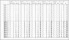
Specific electrical resistance, electrical conductivity, Conductor resistance
Spezifischer elektrischer Widerstand, elektrische Leitfähigkeit, Leiterwiderstand
nach vielen Fragen, bezüglich der Kabellänge versuche ich mal mit folgendem zu helfen.
After many questions regarding the length I try to help with the following
Das Bespiel gibt den Widerstand eines 100 meter langen Kupferkabels mit 1,5mm² Querschnitt an.
The example section specifies the resistance of a 100 meter long copper cable 1, 5 mm²
100m , 1,5mm², Kupfer bei 20°C = 1,19 Ω
100m, 1,5 mm², Copper at 20ºc = 1,19 Ω
I HOPE IT HELPS TO UNDERSTAND THE PROBLEM !
I hoffe das es hilft das Problem zu verstehen !
GREETS
-
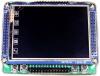
For this thinks, i had to display on the screen, are the technical features from the Core32 big enough.
I will see, when the displays are playing...... (or not)
-
MIOS8 by default updates the SRIO chain @ 1kHz.
8 enable lines => 1kHz/8 = 125 Hz.
I found this in the forum:
at Screenkeys
At 1 MHz, the CPU can execute up to 10 instructions (note that a branch/goto will cost 2 cycles!) - this should be sufficient, considered that the driver is written in assembly.
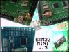
Future compatibility with MBHP_CORE_STM32:
I've proven, that this clock synchronisation method also works with STM32F103, see sid.c driver.
At 72 MHz, there are enough cycles free so that assembly language isn't really required. Even 4 MHz should be achievable.
Alternatively, we could use one of two available SPI ports of the MBHP_CORE_STM32 module (J9 or J16) for full background control w/o bitbanging. This would restrict some usecases (e.g. DOUT SRIO or I2S normaly connected to J9, SD Card normaly connected to J16), but would unload the CPU almost completely, so that LCD transfers can be handled from a background task w/o disabling interrupts. As most application won't require a SD Card, J16 is really predestinated for such jobs.
I hope that this information wasn't too confusing...
When i calculate now.
I see a rate more about 125kHz at 8 enable lines with the STM32 (4MHz).
I need details.
In the Datasheet i´ve read
Correspond to high speed MPU bus interface
- 2 MHz (when VCC = 5V)
-External clock frequency (fcp) min.125kHz typ.250kHz max.350kHz
-Clock oscillation frequency (fOSC) min.190kHz typ.270kHz max.350kHz
and
Relationship between Oscillation Frequency and Liquid Crystal Display Frame
Frequency
The liquid crystal display frame frequencies of Figure 22 apply only when the oscillation frequency is 270
kHz (one clock pulse of 3.7 ms).
1/8 duty cycle
1 frame = 3.7 μs * 400 (clocks) * 8 = 11850 μs = 11.9 ms
Frame Frequency = 1/11,9ms = 84,3Hz
I DON´T REALLY UNDERSTAND, WHAT THE PROBLEM IS..?!
The Displays show only defined Values and Setups. They don´t display any Animated Graphics.
Only 1 of the 8 or 16 CLCDs shows the actual TrackTime.
When my C Programming scills are so good, i will let one of them act like a Anaylzer Display.
Must be the Update frequence so high to drive them with the Enable line over a DOUT PIN?
:question: I´m confused !! :question:
-
-
Erging mir 1000%ig genauso !
Präsentier einfach mal deine Grundidee.....
Viele hier kennen Details, die man als Anfänger, schnell mal kurz übersieht oder gar nicht kennt.
-
Thanks!
The extra writing is not the point...
I had quit Problems with the GLCDs (PCD8544).
They are so "rubbish" and very bad to solder with that small Pads.
After, light touching, the first solder pads torn down.
Thats so rubbish!!!
I will buy the good old CLCD Displays and build this in.
That is a good, old school, choise.
BUT BACK TO BASIC.........
Max. LCD update rate = DOUT update freq / Number of LCDs
Can tell some more details?
:question:? ! the refresh rate is only fast as the 595 (Multiplexer) can switch :question:
For 595, is the switch time from pin to is around 20-25 ns
When i have 8 Enable Lines for the Displays at DOUT Pins, the fastest / maximum Update Rate could be around 200 ns
-
[*]The first goal of the project is to make a Traktor Pro 2 oriented MIDI Controller.
Than is Core32 or LPC a Hattrick !
Sorry, but
the small Traktor Control Surface is breakfast for this..
-
That would be a rather cool ´hood project. Garden sprinkling, synchronized to your newest beats :-)
Some kind like that.....
I don´t think that this a Midibox or an arduino is, but it could be a Midibox! :sorcerer:
-
Hallo there
I´ve read that i can connect / control up to 256 Enable Lines @ ucapps
"Multiple Character LCDs
MIOS32: the standard CLCD driver is prepared for controlling up to 256 enable lines selected via MIOS32_LCD_DeviceSet().
Connectivity: any free pin of the STM32 and LPC17 can be used for the enable line. For instance, if your application doesn't use the analog pins at J5A/B/C of the core module, you are able to connect 12 additional LCDs. You could also program a multiplexer interface in order to address even more LCDs by routing the enable line to one PIC pin.
Wiring Diagram: mbhp_nxclcd_mios32.pdf"
My question is:
Is it possible, to connect the [E] Enable Line from the Displays through a DOUT Pin ?
Greets
Chris
-
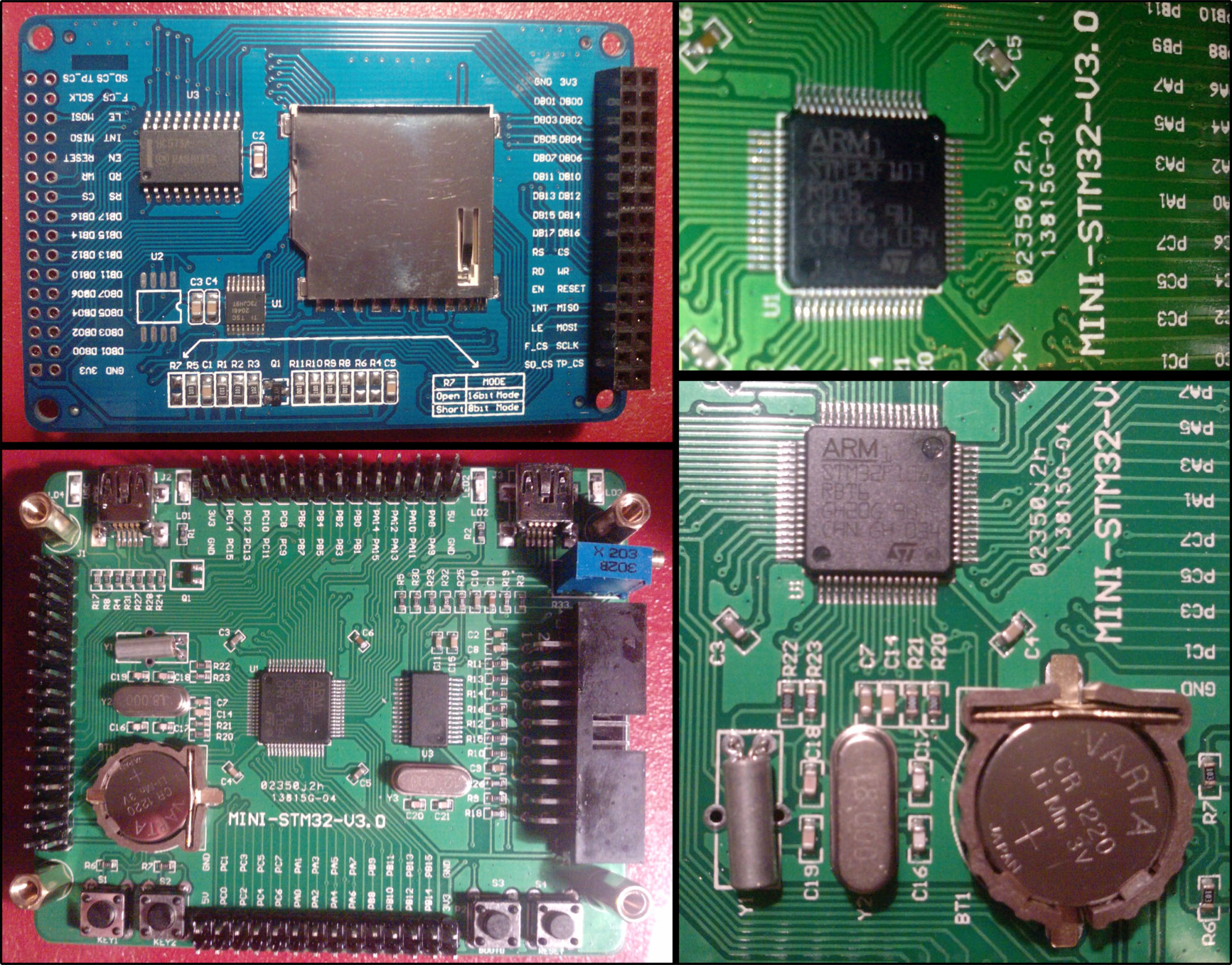
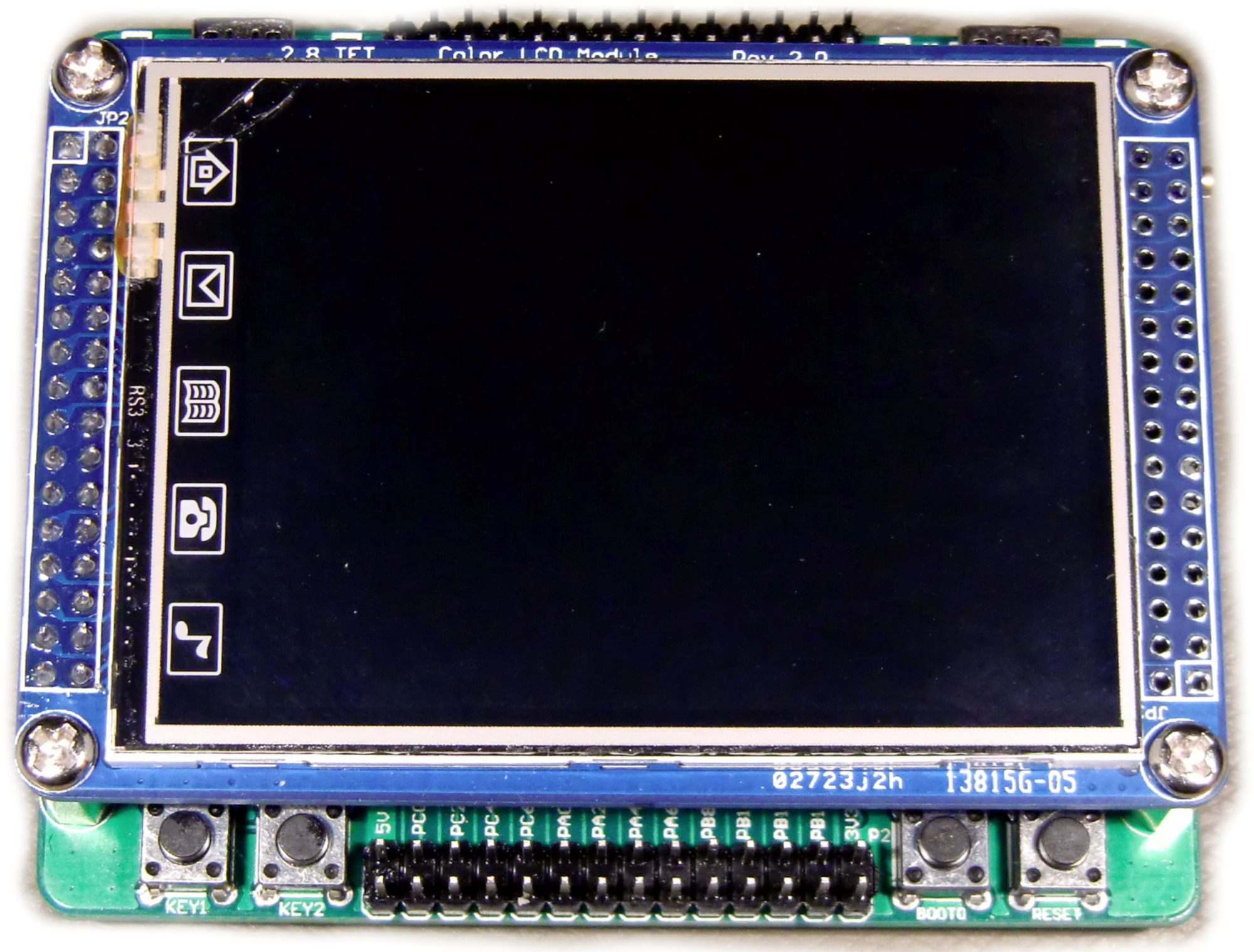
I found this post..
I have this Display and Controller here.
I was loaded with a demo uCOS, and some more.
Also, it has 4-wire Touchpanel and the 8 bit and 16 bit option.
I also tried to implement this to midibox, but i will try this later, when i learn bit more about the system.
First i can let you see, a lot of things, that i became.
I have a folder, that contains a Rtos Demo for this Board.
If someone want to look into the files. i can send it.
There are to many file to attach.
When it helps, have fun.
I found some LCD Driver header and c files. Some members can look into it, so get a better look into the schematic.....
I have wrote the folder name to filename, because i can´t upload a folder.
Mainfolder -> "SRC_" -> Subfolder -> "SRC_LCD"
Have fun!
-
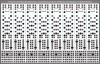
Debug ist auch erledigt.
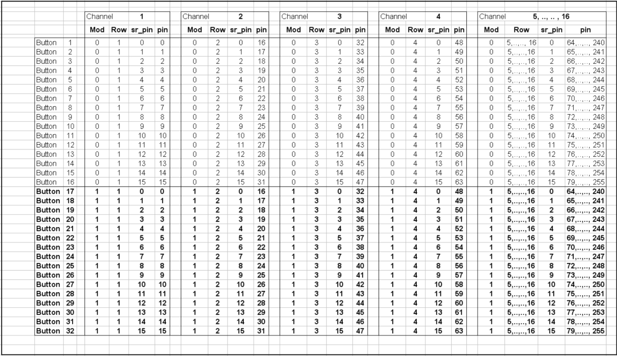
Alle Tasten werden über Debug ausgespuckt. :thumbsup:
Matrix / Mod: 0,1 Row: 0-15 sr_pin: 0-15 Value: 0,1
Vor lauter Bäumen, übersah ich anscheinend den Wald!!! :rofl:
:fear: Geist und Seele bewahrten Ruhe und bewiesen Kraft.
Nach fast 4 Zigaretten, 1 Bier, viel :clover: und vor allem die Schnauze voll, machte ich mal aus reiner neugier,
aus
// each channel has 16 buttons
u8 note = mod*16 + 0x3c + sr_pin; // 0x3c is C-3
// each channel has 16 buttons
u8 note = mod + 0x3c + sr_pin; // 0x3c is C-3
UND es funktioniert, perfekt.
mod(0) + 0x3C + sr_pin (0-15) = 0x3C - 0x4b
mod(1) + 0x3C + sr_pin (0-15) = 0x4C - 0x5b
Was die 16 bei Mod*16 begrenzte oder machte, bleibt für mich ein rätsel.
Nach dem dritten Edit dieses Posts,
danke an T.K. und den anderen.
und schönen Gruß
-
Ãœberraschung?!
"Ja haben wir denn schon weihnachten?!"
Bezüglich Informatikunterricht muss ich dich enttäuschen.
Kenne die Computer seid über 15 Jahre,vom Schneider PC, bis Amiga 500, C64, 386er und und und, aber die Programmierung habe ich nie angefangen.
Mal hier, mal dort, etwas aufgeschnappt und verstehen können.
Da immer wieder "neue" Sprachen kamen, hab ich kein großes Interesse daran gehabt.
C Programmtechnisch absoluter anfänger.
Mittlerweile kenne ich aber "%d" Ganzzahlwertausgabe, Endlosschleife....
aber nicht das genaue Verhalten bei größeren Programmen.
Mit der Zeit, wird das aber schon.
Übung macht den Meister, heisst es so schön.
Habe hier am Anfang zum Teil nur "Bahnhof" verstanden.
Die Struktur der Programm, ist eigentlich ganz simple.
Werde dann mal sehen, was MIOS ausspuckt und nochmal Bescheid geben.
Danke und schönen Gruß
-
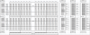
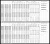
Debug Message gibt nur die Initialisierung wieder, wenn ich MIOS Studio mit angeschlossenem Core32 starte.
Kein tastendruck oder Poti-bewegung wird angezeigt.
Aber Virtual-Midi-Keyboard zeigt das debug tool bei klicken einer Pianotaste an.
Original text aus dem Tutorial wurde ins Programm eingefügt, ohne es diesen zu verändern.
-------------------------------------------------------------------------------
// send received MIDI package to MIOS Terminal
MIOS32_MIDI_SendDebugMessage("Port:%02X Type:%X Evnt0:%02X Evnt1:%02X Evnt2:%02X\n",
port,
midi_package.type,
midi_package.evnt0, midi_package.evnt1, midi_package.evnt2);
-------------------------------------------------------------------------------
Danke und schönen Gruß
-
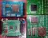
und die Bilder noch!
Möchte keinen Bilderhost aus dem Server machen, habe diese nur nochmal zur vollständigen Einsicht geladen.

-
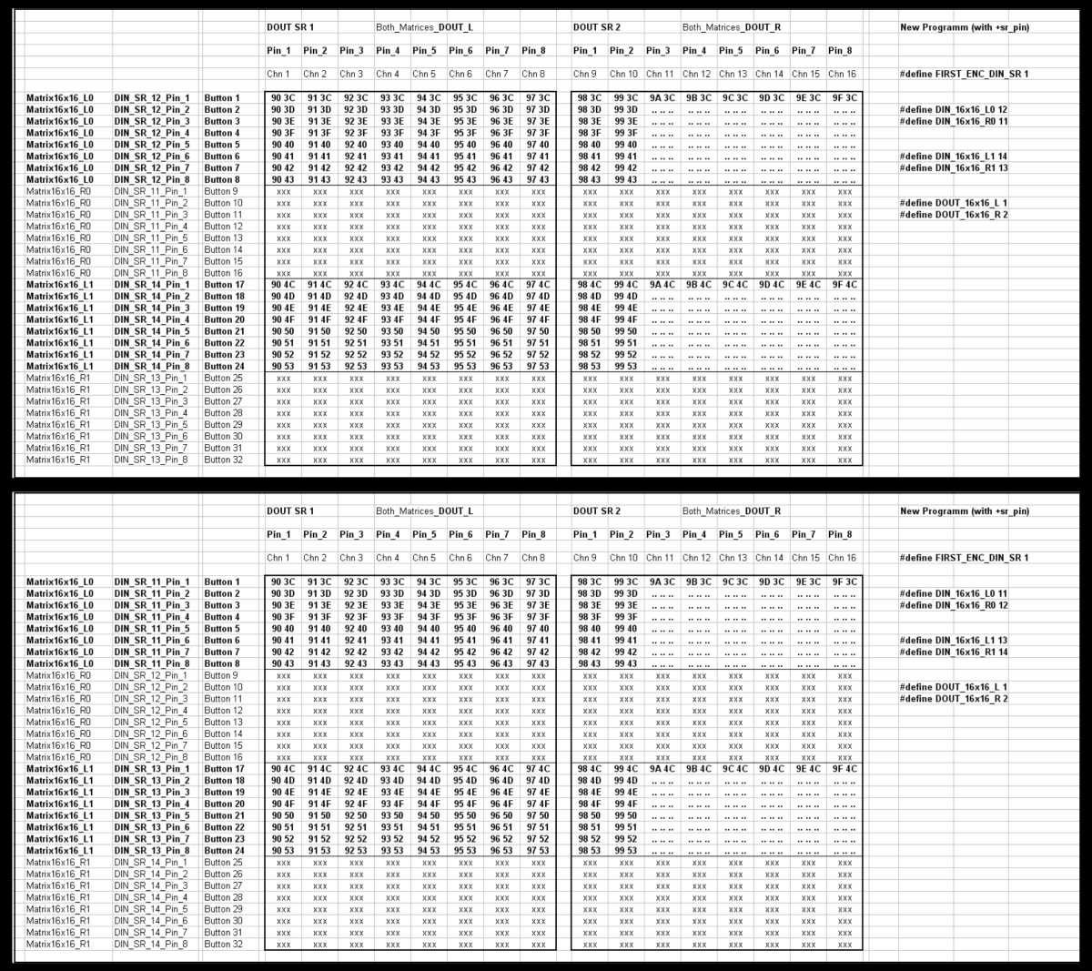
Okay.
Das werde ich versuchen.
Werde dein Programm im Originalzustand lassen.
Habe "+sr_pin" nur mal aus reinem Interesse ohne Ahnung hinzugefügt.
Das mit MOD und ROW ist mir ohne Ahnung, viel zu kompliziert.
Das einzige was ich an dieser Programmiersprache beherrsche, ist höchstens die logic.
Zusammenhänge zwischen Befehlen, ohne Routine, in einem fremden Programm, sind schwer nachzuvollziehen.
Nach dem keine einzelne Note angezeigt wurde, habe ich einfach mal (ohne Ahnung) einige möglichkeiten ausprobiert.
" Es kann ja nicht sehr viel kaputt gehen...... "
Beim dazufügen von " + sr_pin " habe ich ein "besseres" ergebnis, erhalten.
Ich weiss erlich gesagt gar nicht, ob es hinzugefügt werden kann !
Ich zweifel lieber an meinen Kenntnissen als an deinen.
Nun gut.
Habe mal alles nach plan angeschlossen und geschaut was passiert.
AINX4 : R30 wurde entfernt und der Jumper J24 auf 3.3V gestöpselt. <-- Funktioniert alles perferkt!! :thumbsup:
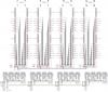
MATRIX : Gleiches Problem. Die -R- Hälfte gibt keine Werte wieder.
-
! Das sind die richitgen Bilder !
R0 und R1 scheinen wieder nicht richtig zu funktionieren.
Für alle Tasten, pro Matrix kommt wieder nur eine Note an.
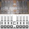
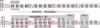
Bei dem letzten AINX4 Board gibt es auch probleme. Die Auflösung ist anders als bei den ersten drei.
Die meisten Potis des DINX4_4 Board an J16 geben mir nur den teilweg bereich wieder.
Alle anderen Potis, Kanal 1 -12, zeigen mir von Links bis Mitte (00 - 3F) und (3F - 7F) von der Mitte nach Rechts, an.
Bei DINX4_4, Kanal 13 bis 16, zeigen sie mir nur (L-Mitte-R) 2A - 7F - XX an
NUR beim 4. Modul an J16.
Habe schon das Modul gewechselt, um zu sehen, ob es am Modul lieg.
Ist aber auch nicht der Fall.

-
NEUE Verkabelung ist fertig.
Alle Matrix Dioden Boards neu gelötet und verdrahtet und Tasten - Platinen durchgemessen.
Keine Probleme, soweit.
Danach angeschlossen und MIOS geöffnet, mit folgendem Ergebnis.
3C und 4C Noten bleiben unverändert. :frantics:
-
DINX4 ohne Brücken, mit original Widerständen...
DOUTX4 mit Brücken, ohne Widerstände...
Dioden mit Kathode zum DOUTX4...
Okay, :thumbsup:
See you later Aligator.
und danke


Need a Program for my Controller
in MIOS programming (C)
Posted · Edited by CSC
Error Update!!!
---------------
I don´t need new Program...
one little complication is still working.
One Button in the Matrix makes a double note, and the last open Shift Register (Shift Register 11) is not reading.
I have 48 (44) Encoder at Shift Regitser 1-11 and the Button Matrices at 13-16...
I replaced the 4 new Encoders at SR11 with 8 Buttons, but it doesn´t work...
finish UPDATE......!
ALL BUTTONS and ALL FADERS, POTIS are alright.
the last and the least 4 Encoders doesn´t want work.
I replaced the 4 encoders with 8 Buttons and filled in, the code, into the program.
but it doesn´t work...
the 4 encoders, that i have planned before, are working fine..
In the program are 48 Encoders placed, but 44 Encoders are working...
What´s the Problem ???
thanks...and greets...