

norbim1
-
Posts
77 -
Joined
-
Last visited
-
Days Won
2
Content Type
Profiles
Forums
Blogs
Gallery
Everything posted by norbim1
-

From the album: norbim1 pics
-
From the album: norbim1 pics
-
From the album: norbim1 pics
-
From the album: norbim1 pics
-
Hi Thorsten, Great news about the KB handler integration. I'm currently planning to build an isomorphic keyboard whit MBKB. ( If somebody interested some theory can be found here: http://www.altkeyboards.com/instruments/isomorphic-keyboards. ) Because of the alternative "non standard" keyboard layouts, it needs a configurable key remapping function. I'm wondering if this would be possible in the future via the NG configuration files? Thanks, Norbert
-
 I think, that the opto LED opening voltage is missing form the equation....It's 1.3-1.5 V typ. In case of 6N138 at the receiver side, the 3.3V supply cannot cause any problem. But it's problematic if you use 6N136 as suggested somewhere. I've some bad experience.....
 -
Put Waveblaster daughter board (Yamaha DB50XG) in a box?
norbim1 replied to SeverityOne's topic in Design Concepts
Hi Milky, I did a small search and found the DIT4096 chip from TI. I think it can do the job, it supports the DB PCM format via hardwired programming. -
Put Waveblaster daughter board (Yamaha DB50XG) in a box?
norbim1 replied to SeverityOne's topic in Design Concepts
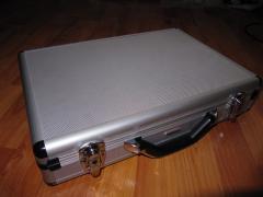
HAMMOND 1455R1602 It's about 165*165*35 mm. Very nice case designed for 160 mm wide PCBs. I like it also and used this type earlier for a USB-Audio module. -
Put Waveblaster daughter board (Yamaha DB50XG) in a box?
norbim1 replied to SeverityOne's topic in Design Concepts
I have my glasses, my head magnifier :) With some practice it's not so hard work. Here are the promised pics. -
Put Waveblaster daughter board (Yamaha DB50XG) in a box?
norbim1 replied to SeverityOne's topic in Design Concepts
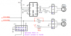
Hi Mike, Attached the schema of my DAC modification. DB60 Codec mod sch.pdf I'll take some photos also, and try to post tomorrow. Norbim -
Put Waveblaster daughter board (Yamaha DB50XG) in a box?
norbim1 replied to SeverityOne's topic in Design Concepts
I'm just finishing a box with the XG60 (NEC clone) based on the MistralXG project (with PIC18F2550, USB). My mods: - The audio output from the card is quite noisy, so I bypass the original DAC on the XG board. I connected the PCM data lines to a small board with PCM1754 DAC with very good result. - Audio input with opamp buffers to the XG60 - Modified Midi routing circuit - SW mod for the PIC (routing, flash for patches, mode selection, instrument selection etc.) Current state: HW is almost ready and working. SW is under dev. -
Hi, I'm in for 8.
-
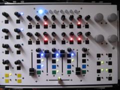
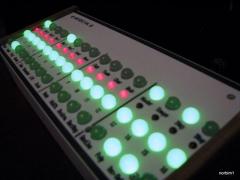
 Thanks for your comments. Yes these are 10mm diffuse LEDs.There is a closer look here:
 -
From the album: norbim1 pics
My front panel solution: illuminated buttons with the original PCB. 10mm green diffuse LEDs for buttons, 5mm red LEDs for the seq disp. -

From the album: norbim1 pics
-
From the album: norbim1 pics
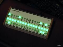
It's working! -
From the album: norbim1 pics
-
From the album: norbim1 pics
-
From the album: norbim1 pics
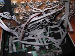
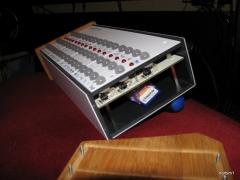
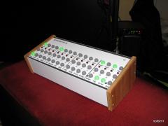
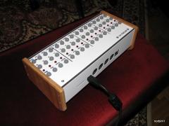
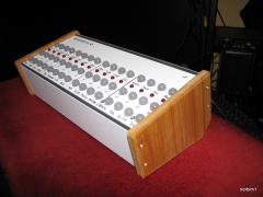
I've just finished my V4L case. -
From the album: norbim1 pics
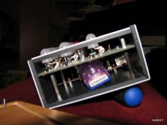
I soldered the cables directly to the front panel PCB, so the overall height can be smaller. There are 12mm spacers between the FP and PCB, 30mm spacer under the PCB. The LPC panel sits on 5mm spacers. -
 Hey, that's really cool. Could You plan to provide the CAD files of this to the public?
 -
Hi Torsten, I found the solution, but it's a litle bit strange: I changed the IC2 from HCT595 to HC595. Even that the schematic suggest HCT595 for 5V LCD-s, my LCDs didn't work with it, but both work perfect with the HC595. I don't know wether others have same experience? Best regards, Norbert
-
Thanks a lot Thorsten, You are right, it doesn't make sense, where the RW set to zero is. I double checked all the connections, also the 5V jumper is OK. I have a 4*20 LCD on my MIOS8, which is working OK, sothe next step will be creating a cross connect cable, I'll try this LCD width my MIOS8 core and the 4*20 width the LPC core. I hope it will show where the problem is. I'll report the result here. Best regards, Norbert
-
Hi Torsten, Thanks for the fast response, first of all, let me say a big thanks for this amazing project. I totally agree with the timing issue, but I'm thinking about the initialization process of the LCD. According the data sheet: It states, that in the first 3 init instruction the RW line should be at zero, but in the code, the RW line set to zero after the first instruction (after the E line pulse). I checked the MIOS8 LCD code, and there the sequence is according the data sheet. So I suggest the following code for the first init command: // initialize LCD MIOS32_BOARD_J15_DataSet(0x38); MIOS32_BOARD_J15_RS_Set(0); MIOS32_BOARD_J15_RW_Set(0); MIOS32_BOARD_J15_E_Set(mios32_lcd_device, 1); MIOS32_BOARD_J15_E_Set(mios32_lcd_device, 0); MIOS32_DELAY_Wait_uS(50000); BR, Norbert
-
Hi all, I tried to use a 2*20 LCD (type JHD202C with standard HD44780 like chip) with LPC core, but it was unsuccesful. After I checked all the connections and soldering, I compared the universal LCD driver with the datasheet. I found in the LCD init part of the universal LCD driver code : // initialize LCD MIOS32_BOARD_J15_DataSet(0x38); MIOS32_BOARD_J15_RS_Set(0); MIOS32_BOARD_J15_E_Set(mios32_lcd_device, 1); MIOS32_BOARD_J15_E_Set(mios32_lcd_device, 0); MIOS32_BOARD_J15_RW_Set(0); MIOS32_DELAY_Wait_uS(50000); In the first init command the RW set to zero after the E line trigger, but I think it should be before. As I haven't install the toolchain jet. could anybody please check that my founding was correct or not? Thanks a lot for Your kind help
