lazenbleep Posted December 29, 2013 Report Share Posted December 29, 2013 HI! About to build my sammichSID at last. I'm interested in using the analog ins with potentiometers. I have seen this is configurable in the asm file, where can I find the inputs A0-A4 on the sammich board. I probably haven't searched hard enough, but I'm guessing the potentiometers act as voltage dividers across 5v? Many thanks, Ben Quote Link to comment Share on other sites More sharing options...
TK. Posted December 29, 2013 Report Share Posted December 29, 2013 Hi Ben, the analog inputs are available at PIC pin #2, 3, 4, 5 and 7 See also this schematic: http://www.ucapps.de/mbhp/mbhp_core_v3.pdf I guess that sammichSID has no special connector for these pins, but you could solder a cable directly at the bottom of the PCB. I'm guessing the potentiometers act as voltage dividers across 5v? yes Best Regards, Thorsten. Quote Link to comment Share on other sites More sharing options...
lazenbleep Posted December 30, 2013 Author Report Share Posted December 30, 2013 that's great, thanks for your help. Ben Quote Link to comment Share on other sites More sharing options...
lazenbleep Posted January 1, 2014 Author Report Share Posted January 1, 2014 So!, on the Sammich board there are unused pads next to 2,3,4,5,+7. Thanks Wilba! This was definitely one of the simplest kit builds I've done, well documented and lots of nice touches on the board, especially the female headers for Sid caps. I'll post some media when I have the pots working Cheers! :# Quote Link to comment Share on other sites More sharing options...
TK. Posted January 1, 2014 Report Share Posted January 1, 2014 Cool! :) Best Regards, Thorsten. Quote Link to comment Share on other sites More sharing options...
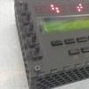
lazenbleep Posted January 15, 2014 Author Report Share Posted January 15, 2014 Hardware done! Used tiny 100k trimmer pots with the legs pushed through holes in the perspex and a small vero board for 5v, ground and divided Vout. Shown also are the cables from the analog inputs, and 0 and 5V from labelled points near to the midi sockets. Thanks for your help, will post when it's working with the software :# Quote Link to comment Share on other sites More sharing options...
lazenbleep Posted January 16, 2014 Author Report Share Posted January 16, 2014 (edited) It works! Here's a little knob test. https://www.youtube.com/edit?o=U&video_id=UvNYcYmuHAg Cheers! Edited May 11, 2018 by lazenbleep wrong video Quote Link to comment Share on other sites More sharing options...
Holypeyote Posted April 6, 2015 Report Share Posted April 6, 2015 (edited) While searching for creating a potmeter extension for the sammichSID I found this topic. So in the setup_sammich_sid.asm I can set (this same parameter can be set in setup_6581.asm, does it have to be set in both files?): #define DEFAULT_J5_FUNCTION 0 to "1" To enable the analog inputs. In the comment of the line it says 1: J5 used for analog inputs - A0..A4 control Knob#1..#5. Does this mean only 5 inputs are available or can you connect 4051 registers to the pins as well to connect more pots. My idea is to create a vero board with two 4051 's and make a breakoutbox with 16 potmeters for realtime control of the sammich. Also where can I set the parameters of those pots. Is this done in j5_io.asm? Edited April 6, 2015 by Holypeyote Quote Link to comment Share on other sites More sharing options...
Recommended Posts
Join the conversation
You can post now and register later. If you have an account, sign in now to post with your account.