

Wilba
-
Posts
3,310 -
Joined
-
Last visited
-
Days Won
2


Wilba's Achievements
MIDIbox Guru (4/4)
5
Reputation
-
Hi Wilba,
Joh here from T'ville Qld. 4814. - Regarding this: Cherry Jammer blog
I would like to know where I can buy a PCB for these Cherry switches?
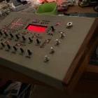
I try to build a MIDI Janko accordion Kbd (for my Tyros3) and have already drilled 123 holes into a 1mm thick Alu sheet and glued these Cherry switched onto it (see Pic). - It' OK, but to make it really 100% I would need more precision; i.e. a printed PCB or machined matrix.
Greetings, Joh
-
Was I gone?
-
That painted engraving is awesome! Even though I promoted the technique of painted engraving on Ponoko panels, I still can't get a great finish every time (which is why I got some Lexan overlays made for the current batch of sammichSID and will sell the spares to past builders very soon, sort of an apology for such a messy DIY process). Can you share how you defined the engraving as Ponoko-compatible? i.e. is this "three-stroke" vector like sammichSID, or raster only, or raster plus vector outline? And did you paint with backing paper still attached to the panel (like is done with sammichSID) or just really carefully and with lots of cleaning up afterwards? P.S. to all: the "easy" way to get the panel cutouts/engraving into Ponoko-compatible SVG is via the published DXF files of the panels, imported into Inkscape. I've been using this technique lately, design in Solidworks, create drawing of all panels, export to DXF, input into Inkscape, combine paths, set strokes, send SVG to Ponoko.
-
My MB-SEQ PCB is basically a combined switch/LED matrix for all the LEDs and switches (1x 74HC165 for inputs, 74HC595 for LED outputs, 74HC595 for matrix "column" sinks), plus dedicated 74HC165 for the encoders, since MIOS doesn't (didn't?) support encoders in a switch matrix, and even if they did, the routing would have been insane... it is actually a lot neater by having the 74HC165 close to the four encoders it is handling.
-
Hi all, After receiving many emails about sammichSID since the "final batch" finished, I decided to do two more batches. One batch I am doing right now and trying hard to get in the post so they arrive before Christmas. There are still kits from this batch available. The 2nd batch will probably happen next year sometime after I get close to 50 more pre-orders. So if you read this message, just contact me via my email address (not PM) and I'll either a) have a kit to sell immediately or b) put you on a waiting list.
-
T1L is definitely mounted wrong. That would explain left channel not working. There is no issue with European vs. American transistors... T1L and T1R are specified as BC547, and that's what I put in the kit. They should be mounted with the flat side matching the silkscreen. As for the other channel not working, it could be due to bad solder joints. For example, the pins of C3L,C3R,C4L,C4R. I also don't know what that pale looking stuff is on both sides of the board... is it flux residue? Did you attack it with a heat gun and burn the solder mask? FWIW nearly all issues people have with sammichSID are due to poor soldering (esp. ground plane pads), or killing transistors by heating them too much.
-
I've updated the wiki. Look here: and here: They are quite easy to fix with a cut resistor lead or wire between pins.
-
I've fixed the broken forum links in the wiki.
-
The LCDs I supply are high-current, they can take up to 250mA but look good at around 100mA (brightness pot at half-way). Since 100mA is a lot of extra current to go through the 5V regulator, the JBL header allows sourcing this current from the unregulated input power, i.e. around 12V. But for some reason, a lot of builders have trouble with this - either the BC337 burns out, or the backlight. I'm not exactly sure why, as I've not had this problem myself. I may have to change my recommendation, perhaps JBL should be set to 5V and let the 5V regulator run a bit hotter, and lessen the chance of burning out the BC337 or the backlight. If you are having LCD issues, please email me directly and I will send you whatever replacement parts you need to get it working.
-
sammichSID LCD troubleshooting help needed
Wilba replied to blake's topic in Testing/Troubleshooting
The ICs being in backwards should not have caused T1 to blow. That usually happens if the current going through T1 is too high, due to the brightness pot being faulty, or if it's at max. and the backlight voltage (when it's set to JBL=12V) is too high (when using unregulated input power). I'd recommend testing the backlight pot as well as replacing T1. If you need more help (or replacement parts), just email me. -
I've been very busy lately and I have not replied to recent emails, sorry. Batch #23/#24 will be posted this week. Batch #25/#26 (potentially the absolute final batch ever) has 30 confirmed orders, and 20 empty places. It will be arranged soon. If you've emailed a pre-order recently, I'll reply ASAP. Sorry for the long delay.
-
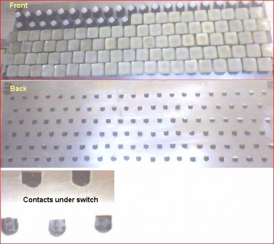
You may have continuity along all the pads connecting the switches with "blue dots" - this just means your soldering is good and the switches all work. The issue can still be a short between ANY pad along those tracks and something else. Perhaps you should desolder the wires going into JD1-JD5 and use a wire to touch pins on JD5 and pins on JD8 at the same time, to simulate switch presses. Observe which ones work or not while MB-SID is running. This might be tedious and boring but you must discover somehow whether the problems are on the CS PCB or on the base PCB. Or at least know for sure that the base PCB and the 74HC165 are all working as expected. Perhaps it's easier to desolder the wires from the CS PCB first, and have them poke out the bottom, so you can test them while the case is closed... i.e. you probably still want the LEDs to work so you can see the effects of simulating button presses. You could perhaps download some of the other troubleshooting apps (or simple apps) that use DIN modules and test just the inputs of the 74HC165... those apps will not use a switch matrix so you should bridge pins/pads to ground, not to the pins of JD8.
-
Easy fix: I will send replacements. FWIW, I buy those exact LCDs from that supplier for the kits. They are good and cheap but about 1 in 50 don't pass my QA due to imperfections with the LCD substrate or whatever... they have some bright green spots around the active area. I test every LCD I sell, because it's less time and effort than trying to troubleshoot someone's sammich* which doesn't show a boot screen :wink:
-
There is a wiring diagram in the wiki pages, scroll down to "Control Surface Wiring" and note the errors in my diagram (was too lazy to fix this at the time, sorry). Measuring voltages is probably hard to do because the switches are in a 8x8 matrix, so the voltage at the 75HC165 input is going to be either 5V for unpressed switches or ~1V for pressed switches, but only for 1 ms in every 8ms (guessing at the actual duration, could be 0.5ms every 4ms. It's 1/8 duty cycle though). Since I have the PCB layout and can highlight the connected tracks, I can see that some of the the non-working switches have common tracks. So it would be more likely that the cause is due to something wrong with that track (short, break, etc). I've uploaded some annotations to your picture, showing which switches are connected... the "input" side of the switch, with the input going into the 74HC165. It can't be coincidence that ALL switches on those common tracks don't work... so it's either something wrong with the cable or the IC pads or something at JD5... It doesn't explain some of the faulty switches, they must be a separate issue. I can't be certain but if you think the LEDs and the other switches are working, then the "current sinks" for the LED and switch matrices must be OK.
-
Sorry, by "pullup resistors" I meant R2 and R12, which are on the two signal lines between the PIC and the 24LC512 ICs (IC5-IC19) Regarding LCD: check the trimpots... I've had some go intermittent due to pressure, i.e. push them in too much with a screwdriver and it loses contact. So perhaps try pressing them to see if that's the cause. Regarding hum: nearly all the time, hum is caused by the input power. Perhaps it's not enough power and the voltage regulator can't produce stable 5V... or the power supply is switchmode and noisy. Also you might get hum if you're feeding the output into a balanced audio input. I would advise checking whether you get the same hum when connecting into a totally different amplifier, different cables, etc. i.e. home stereo or computer line in. If it's still there, then consider the power supply as a cause... it could even be a faulty capacitor or voltage regulator. Regarding LEDs: The LEDs that don't light up are either dead, backwards or have a bad solder joint. Perhaps you can confirm they're working by powering them directly with 5V with a 1K in series. Since the other LEDs seem to be working as expected, the problem isn't with the 74HC595, it appears to be outputting OK. Maybe you just got unlucky and burned a few while soldering. I can send you some replacements if you want, just email me.

