

TK.
-
Posts
15,261 -
Joined
Content Type
Profiles
Forums
Blogs
Gallery
Everything posted by TK.
-
I haven't compared this with my RSAON11M9 faders yet, but I've the impression that the new method leads to better results, not at least because the increased PWM resolution allows more exact control over the speed so that probably *any* fader will reach the target position w/o overshoots. The "sine" function of the MBFM tool moves all faders concurrently with slow target position changes -> this is the noise test -> this allows to optimize parameters for less noise. Can't say more about this topic yet - after this posting I stopped the development, and I will continue in some days. Thereafter more details. Best Regards, Thorsten.
-
When you compare the MBHP_MF_V2 schematic with MBHP_MF, you will notice that the motor control pins are now directly connected to the PIC. The same can be done with the old module - just remove the two 74HC595 chips and use a 16-wire ribbon cable for direct connections between MBHP_CORE and the TC4427 based H-bridges. You should also add the status LED, and a 470 Ohm resistor between the MF potentiometer (P1) and ground for improved voltage control. Note that the MBHP_MF_V2 firmware hasn't been released yet, it needs some more work until it will run perfectly. If nothing unexpected happens I will release it in ca. 2..3 weeks Best Regards, Thorsten.
-
Instead of buying a 47 Ohm resistor you could also connect two 100 Ohm resistors in parallel -> this will result into 50 Ohm, which is ok for testing. Best Regards, Thorsten.
-
Maybe you are playing one or more keys on an external keyboard at the same time? Because pattern changes are not only controlled by the matrix buttons, but also by received MIDI Note On/Off commands. To doublecheck that this behaviour isn't related to a hardware issue, I would propose to unplug the MIDI IN cable after you've ensured that there is no actively played MIDI key. Alternatively you could select another MIDI channel and/or reduce the keyboard zone for the drum instruments (ENS->INS) Thereafter press and depress the PLAY button - this will initiate an internal "all notes off" - just to ensure. Best Regards, Thorsten.
-
Always nice to see what you guys are doing - interesting show! Happy new Year, Simone! :) Best Regards, Thorsten.
-
Maybe you soldered the buttons with the wrong orientation (rotated by 90° - thats hard to do, but not impossible ;)) Jeppe: could you please attach a photo to give us a better impression about the issue? Best Regards, Thorsten. P.S.: happy new year to those who live in the GMT+10 timezone! :sorcerer:
-
Hi Kris, I would propose to test the SC and RC connections between the first and second DINX4 module with the SRIO interconnection test (-> http://www.ucapps.de/mios_download.html ) (see README.txt for further instructions) The SI connection between the first and second board can only be checked with a multimeter, e.g. with a beeper function: remove the last chip of the first DINX4 module, and the first chip of the second DINX4 module, thereafter "beep" the connection between the SER input of IC4 (first DINX4 module) and the QH output of IC1 (second DINX4 module). If this still doesn't help to locate the error, it would be interesting if the second module is working when it's connected directly to the MBHP_CORE module (-> swap first and second DINX4 module) Best Regards, Thorsten.
-
There is currently no advantage if you build this incomplete (!) version - the project is stalled as long as no STM32 derivative with 512k flash and simultaneous access to CAN and USB interface is available. The V3 firmware was only "prove of concept" and some personal C++ practice. It could take another year until it will be continued - or maybe I should just cancel it and focus a new synth? :ahappy: Best Regards, Thorsten.
-
It's probably a wrongly configured encoder type. MB64e uses MIOS_ENC_MODE_NON_DETENTED while MBFM uses MIOS_ENC_MODE_DETENTED2 by default. According to Peter MIOS_ENC_MODE_DETENTED3 is the more suitable one for STEC12E0x Yod: do you already know how to change the setup_mbfm_v1.asm file and recompile the application? (see also README.txt) Best Regards, Thorsten.
-
Relevant for MBSID V1 (not MBSID V2!): - setup_*.asm (the setup file you are using) - src/mios_tables.inc - src/cs_menu_io_tables.inc - src/cs_menu_enc_table.inc There are some comments in these files which you have to read to understand the configuration options. Once the firmware has been recompiled, just upload the resulting .hex file via MIDI like you did before. Best Regards, Thorsten.
-
A strange pinning, I never saw this before... if you are not able to find a better suitable bargraph, you could improve the luminance of LEDs connected in serial by using a 100 or 47 Ohm resistor instead of 220 Ohm Best Regards, Thorsten.
-
You can continue in german if you want. Man spricht Deutsh. ;) Best Regards, Thorsten.
-
Hi Thomas, Yes - to be more exact: MBSEQ MIDI IN3 -> BLM MIDI OUT MBSEQ MIDI OUT3 -> BLM MIDI IN MBSEQ 5V Power -> BLM J2 SR counting starts at 1 (0 disables a button/LED function) The first shift register (SR) is number 1, the second SR is number 2, etc Please ignore this part - for historical reasons MBSEQ supports two different BLM extensions as well, but they are not so powerful as the BLM16x16+X All parameters which are starting with BLM_* are intended for a 4x16 matrix - it's expired and only used by people who used this feature for their MBSEQ V3 All parameters which are starting with BLM8x8_* are only used by Wilba's Frontpanel to reduce the number of shift registers The configuration of BLM16x16+X is very very simple! :) Just select OUT3 for BLM_SCALAR in the MIDI->Misc menu - thereafter an auto detection will be started at this port and the BLM16x16+X will be configured remotely from MBSEQ V4 This picture shows how the menu page looks like: Best Regards, Thorsten.
-
Btw.: the schematics are interesting - I haven't expected that Mackie controls motorfaders with an analog circuit. Thats the way how Rasmus started the MIDIbox MF story some years ago, but we decided to go for total digital control due to the reduced complexity. Best Regards, Thorsten.
-
As long as you don't connect a SD Card or MBHP_ETH interface to J16: - up to 4 DINX4 - up to 4 DOUTX4 - up to 4 AINX4 Number of buttons/encoders/LED rings only limited by the application you will program by yourself. E.g. if you would multiplex 2x2 DOUT SRs to a 16x16 matrix, you could easily control 256 LEDs If you duplicate this multiplexing to 8x2x2 DOUT SRs to 8 16x16 matrices, you could control 2048 LEDs If it makes sense or not would be your own decision - thats one of the reasons why you will never get a straightforward answer. It would be easier for us to give you a helpful answer if you would introduce your plans (and maybe also a bit of your programming knowledge) first and ask for a feasible partitioning of available resources. Best Regards, Thorsten.
-
No - I expected that this "imperfection" can't be recognized, and you proved it - thank you! :) I will release the new version anyhow. Best Regards, Thorsten.
-
Btw.: could you do me a favor? Some days ago I noticed that the timer used for the LED meter handler was called much more frequently than required; this resulted into an unnecessary CPU load of ca. 10% only for meters (instead of ca. 1%). I'm unsure if this really caused any noticable effect (e.g. worse LCD performance), but I feel more comfortable when it's configured as intended. I fixed this but have no chance to test the change on my own MBLC, since it's stuffed with a Core32 module meanwhile. Could you please try this firmware version and tell me, if meters are still working as expected? -> http://www.ucapps.de/mios/midibox_lc_v1_6e.zip Best Regards, Thorsten.
-
Both issues seem to be related to Sonar. MBLC itself is a "brainless" device - it only sends commands on button/encoder/fader movements, and it receives commands for LCD output, LEDs and Meters. It's always up to the host to control them properly. Thats a special feature of MBLC - in the past there were people who build a MBLC with a reduced number of LEDs and Buttons. The layer feature allows to assign a second set of control/display functions to these buttons/leds. The appr. button/LED assignments are done in LC_IO_TABLE_LAYER1 (the second table in lc_io_table.inc) There are some more special functions, e.g. to switch between different LCD modes, etc... see comments in lc_io_table.inc They are assigned to the second layer so that no dedicated button has to be added. Best Regards, Thorsten.
-
You could build two MIDIbox64 and link the cores as shown in this picture: http://www.ucapps.de/midibox_link/tunnel1.gif This gives you up to 128 pot, 128 button and 128 LED functions (no need to add a LCD) For USB just buy a cheap 10 EUR interface from EBay (or build a GM5 module) But before you are starting this project it makes sense to ensure that all functions of 3xOSC can be controlled via MIDI. Are you sure that "total control" is supported by the software? Best Regards, Thorsten.
-
The control surface of your MB-6582 will only run properly with the configuration of setup_6582.hex, please upload this file again. There is no need to select another file just only for changing filter calibration values, as they can be configured in the ENS->FIL menu page (thereafter store the ensemble to make this change permanent) And as a sidenote: the calibration values defined in the .asm files are only taken into account when a "virgin" BankStick will be formatted. Thereafter the values can only be changed in the ENS->FIL page anymore (or from external via SysEx, resp. Rutger's MBSID V2 Editor). Best Regards, Thorsten.
-
After you've entered the OSC menu page, select all three oscillators so that the pitch range is changed for all of them. Thats the leftmost item of this page (OSC) -> has to be set to "123" instead of "1--", thereafter scroll to the PRn parameter and set it to 12 Best Regards, Thorsten. P.S.: I agree with Phil, your appearance isn't really fair - most people don't know the manual, you haven't mentioned it in your first posting. Nils gave an initial hint which is mostly sufficient. No need to call him "dickhead", is this the usual tone in other forums meanwhile? He is really a nice guy!
-
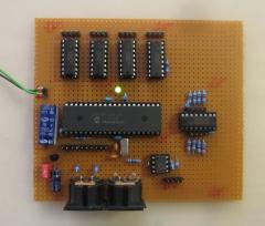
In the last days I worked on a major MBHP_MF update, mainly triggered by Screaming Rabbit who gave me a big package of different Alps faders for free! :) Design Targets: find a solution to handle high-quality faders like Alps K faders with "coreless" motors find a solution for MBHP_CORE_LPC17 which doesn't deliver stable enough ADC conversion results due to the reduced 3.3V voltage range find a solution for MBHP_CORE_LPC17 which cannot handle touch sensors properly without heavy CPU load (resp. without an additional external device or microcontroller) find a solution which is compatible with PIC based projects for best usability find a solution which is DIY friendly and doesn't require additional gear (e.g. chip programmer) for something which isn't part of the MBHP yet find a solution which can be easily tested and troubleshooted (no need to learn new processes) Following circuit is the result: http://www.ucapps.de/mbhp/mbhp_mf_ng.pdf a dedicated PIC controller controls the motorfaders directly it can be accessed via MIDI (only) - this allows standalone usage, cascading (to chain multiple modules), and the re-use of existing infrastructure such as MIOS, MIOS Studio and MIOS Bootloader the module can either be connected to a PC directly, or controlled from a second PIC or STM32 or LPC17 (note that MBHP_CORE_LPC17 has a third and even a fourth MIDI IO port at TTL level so that the available two MIDI IO pairs are still free) native support of various protocols (e.g. PitchBender, CCs, even Logic Control and Mackie Control Emulation) support for 8 touch sensors instead of TC4427 I'm using L293D now - not at least because of the integrated diodes. due to the direct motor control connections, the PIC is now able to generate PWM with 50 uS steps for improved motor speed control while a motor is moved since the firmware is dedicated for this task, there was enough memory free to integrate advanced features, such as runtime-calibration and motor position tracing Two snapshots of the prototype - currently I've only tested the circuit with high-quality K Faders, which were not properly controllable with MBHP_MF_V1 Meanwhile PCBs are available (layout created by SmashTV - thank you!!! :) ) MIOS Studio got a new configuration tool: Especially the calibration is much easier now, not at least because of the new motor position tracing feature: Currently following modes are planned: [*] PitchBender Chn#1..#8 [*] PitchBender Chn#9..#16 [*] CC#07 Chn#1..#8 [*] CC#07 Chn#9..#16 [*] CC#16..#23 Chn#1 [*] CC#24..#31 Chn#1 [*] Faked Logic Control [*] Faked Logic Control Extension [*] Faked Mackie Control [*] Faked Mackie Control Extension There is no real need to add more modes, considered that MIDI events can be mapped on the host PC and/or from another microcontroller (like Core32) which uses MBHP_MF_V3 as a companion. By using Pitchbender events, the highest resolution (10bit) is available. More about this topic (e.g. test of different motorfaders) after holidays. :) Best Regards, Thorsten.
-
0xb1 0x4a will be sent by the pot at the third row, second column. What happens if you turn this pot to full-left or full-right? If nothing happens: the pot isn't properly connected, check the connections! If full-left outputs 0xb1 0x4a 0x00, and full-right outputs 0xb1 0x4a 0x7f, and if jitter stops: replace the pot! Best Regards, Thorsten.
-
 Bingo! :)
 -
-
