Wilba
-
Posts
3,310 -
Joined
-
Last visited
-
Days Won
2
Content Type
Profiles
Forums
Blogs
Gallery
Everything posted by Wilba
-
I WANT
-
I've sent invoices to the last remaining orders. I have 5 OPL3 chipsets left (1xYMF262 + 2xYAC512).
-
dj3nk
-
klugscheisser
-
Excellent case design! I've wanted to use that Retex case for a long time, so it's good to see how someone else used it.
-
nILS
-
Are you measuring 3.2V on the AC lines using AC setting on your multimeter? If so, there's not much hope fixing this PSU. Internally, it's just a transformer with two 9V AC secondary coils, one leads directly to the output pins, the other goes through a bridge rectifier/voltage regulator to supply 5V DC. I'm no expert but getting less than 9V AC on the AC output pins suggests a short somewhere on that coil, i.e. less coils, less output voltage. As far as I know, fuses either pass all the voltage or burn out and pass nothing, not drop the voltage.
-
Those voltages suggest a sagging 5V supply or some kind of other problem perhaps... 9.05V on the CS pin is bad, that suggests CS pin is being shorted with the 9V supply to the SID. Maybe you got the CS pin wrong and you were really measuring the Vdd pin (pin 28)... but in case you were really measuring 9V on the Vdd pin, you should check voltages everywhere. Do not insert the SID chips again until you fix this problem! You do not want to be putting anything over 5V into the data I/O pins! It is possible that you have made some wrong connections setting up the PSU Option A or B... please check these first and check the voltages of pins that should be 5V and 9V (assuming you're using 9V SIDs like 6582/8580)... specifically, the supply to the 74HC595 underneath the SID sockets and the PIC. Take out ALL the ICs in the entire board and check voltages everywhere! The interconnection test should be run without a SID in the socket.
-
I think it's just package differences. YMF262 datasheet shows the YMF262-S as a 48-pin SQFP package (small quad flat-pack)... The YMF262-M is the more common 28-pin SOP package (the ones found on most sound cards, the ones I sell and the ones used by the OPL3 module). I don't know what the YMF262MEZ would be, most likely a different package... that would be consistent with the suffix of other IC part numbers.
-
WD-40 is not a lubricant. Just thought I'd mention that... Whatever lubrication occurs is purely accidental ;) FWIW my Dad cuts stainless steel with a very slow drill speed and uses lard as a lubricant.
-
People ordering after the first batch were packed and posted haven't received invoices because I've been pretty busy or pretty lazy... :-[ I'll get onto that tonight... ;)
-
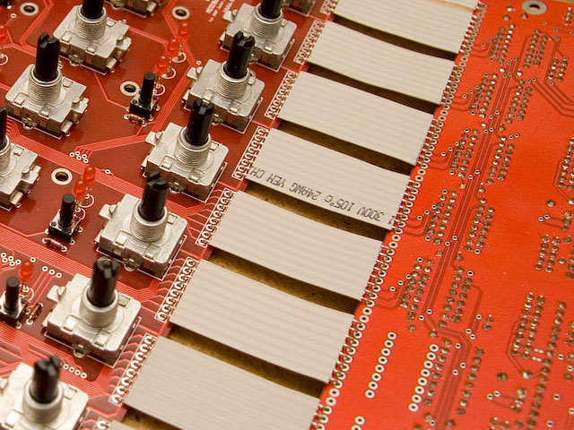
I don't think there'll be a problem... although I suggest stripping the wire and putting a 90 deg bend so that the wire lays flat against the PCB, like shown in this picture... that helps avoid stress on the wire as it bends. The picture is before I soldered the joints... soldering both sides also helps avoid stress on the wire where it is in the hole, i.e. the 90 deg bend won't be repeatedly flexed and then break because it's inside the soldered joint.
-
rock the microphone
-
pink
-
I didn't know nILS was a curry muncher... http://www.youtube.com/watch?v=YyssG_brCTk
-
I have both the 7-pin DIN sockets and the DPDT rocker switch, just like the C64. They're new and cheap.... 2 AUD each. I could probably post for 2.50 AUD.
-
MIDIBOX SID always formatting bankstix, even when none connected
Wilba replied to djvinz's topic in MIDIbox SID
You should also check you have R2 and R12 (1K resistors) connected to the IIC pins; See schematic: http://www.ucapps.de/mbhp/mbhp_core_v3.pdf Perhaps your PCB doesn't have these or the connections are bad. -
Process Lasso v3.62.1
-
I think he meant the first post... Done (using moderator super-powers)
-
If anyone's ordering some, can they add some extra for me? ;) Send me a PM... I wouldn't mind getting a few samples of other heatsinks from that store.
-
Good to hear it's all going... can you post some show-off pics? ;)
-
Make sure there's no shorts between LCD and the control surface PCB. (Hence instructions to solder cable to "bottom" side of LCD, and use something to insulate pads on the "top" side, like sticky tape. Perhaps initially try with LCD not attached to control surface PCB. Do you get any backlight or black bars on the LCD?
-
on a related topic...
-
Maybe you didn't put a jumper in J11 to select which Core is connected to the MIDI Out port. Thus you're not receiving the upload request from the Core. Note also you'll need to change the device ID in MIOS Studio to target the upload to each Core (the PIC with that device ID already set). If you get PICs from SmashTV, they will already have ID 0,1,2,3 set and printed on the label.
-
Are you crazy? Desoldering braid/wick is awesome!