Wilba
-
Posts
3,310 -
Joined
-
Last visited
-
Days Won
2
Content Type
Profiles
Forums
Blogs
Gallery
Everything posted by Wilba
-
I agree! ;)
-
Or... just put a link in the readme? http://lmgtfy.com/?q=1+khz+sample
-
The questionnaire I made people answer when going on my bulk order list shows about 90% of people want Doug's panel/case solution... I think that's part of the attraction of using these PCBs (btw just look at the thread title!), so people can have a good and cheap solution for the panel and case, rather than spending a lot on just an FPE panel and still having to buy/build their own case.
-
No, it could not be ;) I've done the interconnection test for every pin, also checking adjacent pins are not 5V, testing directly on the YMF262 pin (i.e. above the solder joint!) No, it could not be ;) I compared with a 1kHz sample. and just for completeness, I pulled out the wire to D2 and clamped D2 to ground... and I get 500Hz (well it sounds an octave lower than 1kHz, can't say exactly what frequency it was). So I don't think it's D2 being grounded. Well I've only tried the default patch with MIDIbox FM firmware, and I have no reference to compare whether this sounds right or wrong. As above, I've already checked continuity and done the interconnection tests. I power the ultracore with a ~7.5V DC input from a "wallwart", that goes through a bridge rectifier and 7805, and I connect this 5V/ground supply to the OPL3 module... and I have a separate bipolar power supply (mains transformer, bridge rectifier, caps, 7812/7912, etc.) supplying the +12V/gnd/-12V to the OPL3 module. (I'm reusing the one I built for AOUT_NG, it's worked perfectly for that). Because I'm not concerned with ground loops at the moment (I just wanted to get it working)... the grounds from both power supplies are connected on the OPL3 module.... i.e. I have a +5V/gnd wire pair connecting Core with OPL3. I just discovered an interesting phenomenon: when I power off the bipolar PSU while the 1kHz tone is playing, sometimes it changes into a 500Hz tone, then I can turn it back on and get the 500Hz tone. Sometimes it just goes silent. Sometimes it resets the Core. However, if I power on the bipolar PSU after I boot the Core, then there's no problems. Also there's no problems if I power on the bipolar PSU before I boot the Core. Strange things happen only if I power off the bipolar PSU while the Core is still powerered. Maybe introducing spikes on the common ground makes weird things happen... resetting the YMF262 etc. I fully expect this issue to be caused by some simple little oversight and be thoroughly embarrassed :) therefore I wouldn't be posting here unless I'd really done every possible test multiple times and tested for continuity, shorts, voltages, etc. multiple times. I think I'll swap the YMF262 with a salvaged one now... at least I'll be doing something constructive, I'm all out of other tests.
-
pft...
-
The section REQUIRED AND WILL INCLUDE IN BULK ORDER is what you're looking for. http://www.midibox.org/dokuwiki/doku.php?id=wilba_mb_seq_parts_guide We can safely assume everything else is not worth my trouble, especially since most builders would either have this stuff lying around or can get it easily... i.e. even I can get this stuff from Australian electronics shops, which are pretty pathetic in comparison to the rest of the world.
-
btw I'm still stuck! I don't like troubleshooting by randomly swapping things... I can't see how the ultracore, or the OPL3 PCB could be the problem, and have full confidence the pre-built testtone firmware should work... I might try swapping the YMF262 for a salvaged one, but even this is a stretch of logic (like I bulk-ordered a batch of crippled YMF262?)
-
There are headers above each SID with input/ground/output. If you're not connecting feedback pots to these, you should put a jumper between input and ground.
-
I don't know much about self-etched boards, but can't you clean up the copper with something? No disrespect towards SmashTV's boards... they've got solder mask and ENIG plating, but I'm so used to double-sided boards with plated through-holes that I found the OPL3 board a bit of a step backwards :) and really missed the solder being sucked into the hole instead of blobbing on top. I think once I've got this OPL3 fully working, I might work on a new double-sided OPL3 module PCB with slightly better component placement... maybe with a Core on there too, and MIDI/audio sockets... or maybe I'll just get nILS to do it :)
-
The MB-6582 base PCB contains the "optimised PSU".
-
Using standard PT-10 panels for MB-6582 front panel?
Wilba replied to m00dawg's topic in MIDIbox SID
You can get FPE to put the corner mount holes on one of their panels... either refer to the PT-10 drawing or I'll upload an FPD file with the corner mount holes. However, you'll have to work out the right size for the countersink... that's probably best done with your intended screws in-hand. I actually used 1/8" ones since I couldn't find M3 in countersink head. Note also, it's easy to make any screw black if you have a Sharpie :) -
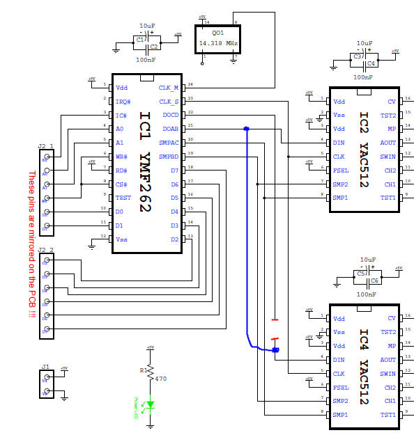
Both. It's an output pin and should be unaffected by what it's connected to. Yes. Well... I am not entirely sure, because it sounds like a toy keyboard's piano patch :) and every second (or third, fourth etc) note sounds like it's louder or has a higher-pitch "tink" to it. What final bit of doubt? :) OK I did this anyway. Both YACs work identically. Connect to DOAB pin, they produce 1kHz testtone. Connect to DOCD pin, they produce silence. Logic seems to suggest that DOAB and DOCD should have identical output "characteristics"... since they're identical data streams intended to go into identical DACs, etc. I can rule out PCB mistakes between YMF and YAC because I even lifted up the DOCD pin and touched/soldered wire directly to the pin, from a known-good "this wire made the YAC work" state. Therefore the problem is either: A) both YMH262 I soldered do not output on DOCD at all, ever. B) both YMF262 are not having the correct registers set. I am liking B as the more likely explanation, but I can't find any problems between Core and OPL3 module, I was using a PIC18F4620 in an ultracore PCB... I've since switched to a PIC18F452 in an ultracore PCB, with MIOS 1.9f (freshly burned with bootloader also). Uploaded testtone multiple times. Uploaded interconnection test also. I do notice A0 isn't exactly 0V when not logic high... it's 0.11V... I guess this is because RD5 is also being used in J15 for LCD comms, so my meter is averaging it (i.e. it's 5V 2/100th of the time). BTW nebula did you get your OPL3 working? Has anyone validated the OPL3 chipsets they got through me are all working perfectly?
-
F
-
T
-
W
-
Using standard PT-10 panels for MB-6582 front panel?
Wilba replied to m00dawg's topic in MIDIbox SID
Also the standard PT-10 panels are not anodized, very prone to scratching, and have holes in the corners which you may not need/want (if you can get the countersunk screw glued to the back). Load up the FPD file and look at the difference in cost... $108.74 vs. $96.39. Half that saving would be lost just in shipping the panel to FPE, so I gladly pay the extra $6 for black anodized aluminium :) -
I finally finished off my OPL3 module, using the OPL3 chipsets I got from the bulk order. Good news: They work, sort of. Bad news: They work, sort of. Here's the troubleshooting log so far. NB: I refer to parts by references on schematic PDF, actual part references on SmashTV's PCB and website are DIFFERENT! I uploaded the FM testtone app and only got the 1kHz tone on channels 1+2. Tested connectivity in the opamp stages and voltages, all seems OK. Swapped around opamp ICs to prove they all work fine. Took out IC5 and bridged between IC3:O3 and IC5:O3, got audio out of channel 4. Also bridged between IC3:O4 and IC5:O4, got audio out of channel 3. TL074 in IC6 seems to be good (and tracks between IC5->IC6). Probed with noise generator (aka. my finger attached to a resistor lead) at IC4:AOUT and get buzz on channels 3+4, otherwise it remains perfectly silent. Note probing on IC2:AOUT results in same kind of buzz on channels 1+2 mixed with the 1kHz testtone. Therefore, TL074 in IC5 seems to be good. I was fairly confident also that the YAC512 in IC4 must be good too, since it's taking in input at pin IC4:SWIN and outputting it to IC4:CH1 and IC4:CH2 into the opamps and making sound on channels 3+4. So... I cut the track going into IC4:DIN and connected IC4:DIN to IC1:DOAB.... in other words, make both YAC512 use the same output from the YMF262 - the "known good" 1kHz test tone signal.... and I get test tone on channels 3+4!!! Note also, if I leave IC4:DIN open (floating), it goes into insane noise mode as you would expect from garbage values going into a DAC and then amplified. Therefore, I am pretty certain that both YAC512 are perfectly fine, and that the problem is the YAC512 in IC4 just is not getting any test tone signal at all. I ran through possible problems between YMF and YAC512 and they are just not there. The connections are good. IC1:DOCD to IC4:DIN is good. All pins of IC4 in common with IC5 are good (and this is backed up with IC4 working and making sound if connected to IC1:DOAB) Connectivity between PIC and OPL3 is all good. (I doubt I would get any testtone at all if this connection was bad - the registers would be garbage). I was trying hard to pretend I only had one YMF262 (i.e. to help others in future who really only have one YMF262)... but I had run out of ideas and I really wanted to know if it was a broken YMF262. So I replaced the YMF262 with another brand new one, and the problem is the same! I am assured that I should expect the testtone on channel 3+4, but right now I can only start thinking up unlikely explanations such as, the YMF262 really is not outputting on channels 3+4, since the output on DOCD pin is 0.28V (effectively logic low all the time?) whereas DOAB is 2.24V (an average of logic low and high?) What else could I possibly do to work out what's wrong?
-
The real fools are the ones that made posts suggesting these weren't real (or posting more false details) and spoiling this April Fool's prank for others. Really, was it so hard to have a laugh and not post anything? No, you just had to post something to prove you're smart, but not smart enough to play along and let others be fooled. You are akin to those social retards that post spoilers in the comments section of torrent download pages. "What a great final episode of 24! What a pity Jack Bauer had to die in the end." To the real fools, your names* have been recorded in my big black book of people to whom I will never sell anything ever again, likesuchas SIDs, PCBs, LCDs, knobs, rotary encoders, switches, LEDs, complete MB-SID kits with pre-cut acrylic cases and whatever else I might acquire in my bulk order madness. * except Goblinz, you're still a fool but catching the 104 reference has attenuated my annoyance with you
-
The pages says he used a permanent marker, followed by varnish.
-
The 6582A shipment came in this morning, and among the tubes of 6582A, I discovered 13 tubes of 13 SIDs marked with 6583A At first I thought this was just a misprint, a mistake at the factory... but then I did some testing. Conclusion: It is a SID and the filter is different to any other SID I've heard. The resonance is phat. Here's a quick demo I recorded (I had to rush it, I'm already late for work!!!) First you hear the 6582A, then the 6583A: http://www.mb6582.org/temp/6582A_vs_6583A.mp3 I can't keep all 13 tubes of these, that would be a little TOO greedy even for me... I think I'll keep 5 tubes and share these among the MIDIbox builders who have done me favours :) that leaves 8 tubes 13 SIDs... so it's 104 that I will now share with the MIDIbox community. Just post in this thread if you want some. I will randomly select one lucky person to receive 8x 6583A SIDs. I will then randomly select 48 people to receive 2x 6583A SIDs each. If there are less than 48 people posting in this thread, then some people might get more than 2x 6583A SIDs. I will end this lucky draw in 24 hours, so the regular forum readers get a better chance of getting some (more?) of these. People are welcome to make me obscene cash offers for some of these, I will consider any serious offer. :) Only post in this thread if you are serious about wanting some 6583A SIDs.
-
This guy (inventor of SID feedback pots?) coloured some knobs for his C64 mod, but then didn't use them: http://www.bigmech.com/misc/c64mods/misc.html I plan to do this one day with the white Waldorf knobs... though maybe do a colour blend so they are darker around the edge, and varnish with a brush.
-
From nothing to 2 working SIDs?? (mono6581 and MB6582)
Wilba replied to jooks's topic in MIDIbox SID
Hmmm... so the problem fixed itself, or perhaps you didn't run tests again after reheating joints... I suppose it doesn't matter, you will know soon enough if Core 2 starts to fail again. That problem is easily fixed.... just click on the under my name :) **edit** LOL you already did.... -
From nothing to 2 working SIDs?? (mono6581 and MB6582)
Wilba replied to jooks's topic in MIDIbox SID
That is to be expected, because the IC socket pins are not as long as an IC and not designed to mount into another IC socket. It is a much looser connection, which is why I use this "double socket" when I'm moving a PIC between a PIC burner and a Core; it's easy to put in and out, no need for an IC removal tool, and no wearing out of the IC socket. After a bit of thinking, my best hypothesis is that somehow there's a difference between the PIC pins in Core 2's IC socket and your wires... and it may not be the pins connecting to the crystal, it could be any of the Vdd/Vss pins or pin 1 (reset pin) which by being bad/intermittent, cause the PIC not to boot up properly. Even if you test this in-situ with a PIC installed, an intermittent contact on the crystal pins might cause the PIC not to get a good oscillation and thus not boot up. You might want to try a few other tests - like inserting a known good PIC into Core 2 only half-way, test, then try pushing it in down very firmly, test again. Perhaps also check how you've bent the pins on the PIC, that they're all aligned the same, it's symmetical, they all angle slightly inwards instead of outwards (like they are when "fresh") or exactly vertical. You want them to go neatly into the IC socket pins, that the ends of the PIC pins align with the place the two sides of the IC socket pin touch each other. If they're bent too far inwards or outwards, it makes inserting the PIC difficult and might cause a bad contact. The other alternative theory is, perhaps the IC socket pins have been damaged or widened too much and do not have enough grip on the PIC pins... let's say for example it's the crystal pins, those IC socket pins work when there's your wire plugged into them but not when there's a PIC pin... perhaps the wire is wider and makes a better contact. Inversely, perhaps the other IC socket pins make a better contact into the IC socket than the PIC pins. At some point, you might have to just replace Core 2's IC socket, which is time consuming but not too hard if you cut between the socket's pins and remove them one at a time. -
From nothing to 2 working SIDs?? (mono6581 and MB6582)
Wilba replied to jooks's topic in MIDIbox SID
Actually that's cool... the idea worked, AND you proved you didn't need to desolder the caps/crystals on Core 2 AND you showed pics so I believe you :) It seems the only difference is the way the PIC is "seated" in the Core 2 socket... Let's assume you were very wise and bought more than one extra 40-pin IC socket :) now try to put the PIC in this loose IC socket and then put both into Core 2. So basically the same as the second picture, but without the bent pins/wires. If that makes things work (and based on your results so far, that's just as unbelievable but still possible) then you've narrowed things down even more. I am approaching the point of being stumped.... not quite there yet, I can still come up with some more tests to do, but running out of ideas. At least we know the parts are good, and it really is only a contacts/joints problem. -
Great job, Blixman!!! Congratulations! White panels look really cool. It looks like a FPE/Schaeffer panel, but how did you get it in white? btw I think a red/black LCD would look perfect with this... http://character-lcd-lcds.shopeio.com/inventory/details.asp?id=1287&cat=Lcds&sub=Character%20Lcd or... I just remembered... I could send you something like this for free... I just got a box of them with amber backlight, but it is easy to swap the amber LED for white. http://www.crystalfontz.com/product/CFAH2004A-TFH-JT (to be honest, the text looks more like this one: http://www.crystalfontz.com/product/CFAH1602L-TGH-JT)