Table of Contents
ToS - Traktor Controller Blog
The quest
- Found uCApps
About a year(or more) before this project was started, I accidentally stumbled upon a ucapps'es MIDIBOX Gallery, back then I haven't realized what this was all about(a free code, open architecture, everything on a plate…) so I just carried on.
Traktor 2 made me do it! Traktor made me start a quest for a midi interface that is suitable for live mixing(bkz with only one mouse/keyb and two handz It's….ludicrous to make a mix the way I want it to be). So what else would I use but G and within the(mostly crappy) search results was:… yees, u guessed. At first I wasn't aware what I've stumbled upon, just copied the link for later, but, after few days I came back and read about the project, the variety of layouts, the beauty of it all. Since I'm good with electronics (well…better than many) & computers I've decided to make myself one.
- Made a layout
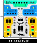
Layout below is approximately a version 2, 2.5 and there are still changes to add(mostly Traktor 3 compatibility).
- Ordered core chip (there were nowhere to be found in my town so one of electronic shops oredered 5pcs just for me to buy one :D, hopefully that won't be the las one I bought )
- Ordered other electronic parts
After one week, when a chip arrived, I made a list of all parts and went to the electronics shop(like 10minutes before they're supposed to close).
The part of dialogue was:
-clerk: “What, you need all this NOW?”(worried face)
-me: “Weellll,(stalled a bit) no.”
-clerk: (sigh)“Good, drop by tomorrow, it will be ready for you.”
The thing I like about that shop is that there is like 3,4 female clerks and they're all nice to the customers. The next day I didn't bring enoguh money(actually, almost no money) luckily I had a friend with me so we managed to cover the price(using the coins(nickels, dimes,…)).
- Ordered PCBs, after 2 weekz, got them. [core, AINx4, DINx4, DOUTx4, BURNER]
And then there was this stall bkz I couldn't decide what to do about etching(to make PCBs or to order them to be made for me by professional etching workshop). I'm quite glad that the descision was the latter one(and a bit expensive).
The torment
- built the burner
When I got the PCBs I was happy like a little girl discovering an orgasm(though I don't know how it looks like), nooo, I didn't run off to home and my (untrusty) soldering iron. I've finished all the bussiness that I had and then headed towards the home, easily. Came home and soldered deeply into the night.
- problems powering the burner
See, I don't have money to waste so I've decide that I dont need two(stinkin') 9V batteries(after all, I can buy for that much money 2-3 pots). So when the burner was done I searched around the house for a power supply with enough voltage so I can fryyyy mie PIC. Guess what, I found it…a Pentium 1 AT power supply. You see, these supplies have +12 and -12 volts output and I thought to myself, “Well, that should be enough…”. It was enough but it made sparks, fireworks out of my MBHP_BURNER's PCB. People don't make this mistake!!
Forum link with details
- Flashed the pic
- midi cable out of mouse cable
- switching +5 & ground
Since I was using J11 to connect CORE with gameport with standard 3 pin CPU Fan connector CORE side i accidentally switched sides of J11 and connected:
J11[IN] ↔ PC[IN]
J11[OUT] ↔ PC[OUT]
J11[Vcc] ↔ PC[GND]
Funny thing, I got the problem with swapped IN/OUT and swapped them on connector but i got another pcb line burned out. Luckily, MIDI is built to send data in negative logic(high voltage is logical 1 and low is 0) so there was not much inverted polarity. Nothing happened to the PIC. [To bE CONTINUEd…]
- troubles about uploading MIOS
- got LCD from Sasha Djurich
- found a reason why MIOS upload wasn't workin'
I've replaced CORE R6 (1.2k) with 100R and since the MIDI sending is done in inverse logic the PIC wasn't receiving enough-ly variable voltage while sysex was beeing sent.
- start of programming & case quest
I've decided not to make cables nor connect modules to the core until I find a good case to be recycled for my BOX.
- casing
Soo, one less Commodore 128D on this planet. It is the American version with full metal casing. It's heavy, darn heavy and has a built in PSU so I don't need to bother. The plan was to, strip everything that can be stripped from the main board (resistors, caps, diodes…) except for the integrated circuits, then make holes in the C128 pcb so I can mount CORE and other pcbs ontop of existing ICs the way that they are used as spacers. To tell you the truth, it works like a charm, it is easy and fastest mounting I've ever done. I have evicted the 5.25“ FDD and used It's [door knob] hole for front headphones jack. Don't know how to seal the 5” floppy cut. Now I have a large case with built in PSU(euro connector(aka PC style), power switch, sexy red power diode included) and ~midi connector on the back that was left on the old board and wired to the core. Usefull dimensions are: 415(w)x309(h) mm
Heh, I have space, why not use it.
- pots from sasa
received 35 fine pots, nice hardware, nice price.
- fried the 4x20LCD
Ever tried to swap data lines with control/voltage lines, well, dont! I did(unintentionally) and the result is fully functional LCD with input logic fried. No LCD for the next month.
- idea of connecting front plate with electronics [3×40 pin-EIDE connector style]
with so many soldering I'll probably go nuts but the final product will be…clean and easy to disassemble. And there is no need to buy new flat-cable because I can use my old IDE cables all with connectors attached. Hassle free.
- effects selector [just a pot, needs research / coding]
This function is specific for TDS3 since it has 6+1 effect for each channel.
Effects selector(pot or encoder) should have a custom function assigned to it(along with sending CC value), so when you switch with it to another effect the 4 effect-buttons-state-LEDs should change their state to the one that was last time that effect was on. So on affect change there is:
–store current state of buttons (for old effect)
–restore selected (new)effect's state
–send CC
- VU meter
testing…
- x-fade
I found a mixer crossfader(StageLine MPX-460) for reasonable price (8€). The initial plan was to install a 4.5cm Infinium optical xfader but this one will do the trick just fine, at least for starters.
- jog dials
- Puting together
Three layers of paint: white(to amplify the next color), fluorescent green(UV reactive) and black framing. Glyphs, pot marks and stuff is printed on sel-adhesive transparent foil but in negative(glyphs are transparent and backgorunt is filled with black). Plan was to overlay that foil with another which is just transparent(to prevent scratching).
Final note:
[the casing & faceplate]
I am not satisfied, there is a number of small imperfections:
- some pots are off by few milimeters, one hdd plater is by 3mm to high and overlaps part of a button
- holes for some buttons were not done quite right (too tight or too wide)
- printed layer is well printed but some glyphs are a bit off and it does not stick well to the surface(when bent over the edge or pinned down with button or screw).
- I did not manage to apply protective layer of foil to prevent scratches
- I made quite a few scratches while setting-up controls(and I'm curently half way there)
- casing is well built but now I have some problems with it (some controls don't fit)
- the black that I have used is not scratch-proof enough
- there is more…
Anyway, next time I'll go for CNC-cutted face with engraved or silk-screened letters & glyphs.
[midibox itself] …yet to be tested but there probably won't be any problems.
Scratch/wind/select plates [needs research & development]
touchsensors on scratch plates [research how to connect rotating touchplate with non-rotating signal wire]
Scan turntable spin rate with optical mouse [abandoned: found sometinhg better]
Jog dials will be made from HDD platter (Maxtor slim version 20-40GB, single platter). I have stumbled upon this discovery quite accidentally. Main data platter is about 95mm in diameter, it has mounting system(to the 7200rpm driver) that provides easy maintenance and implementation. The driver(electro-motor) is mounted on three points, below main panel(the only thing that needs to be made is a metal ). The data(scratch) platter is somehow connected to the base of the drive so touch sensor pin can now be easily connected to a point that is not spinning and still sense the touch on the scratch/data platter surface.
Status: This is still a concept but I have here three of such plates and even if they don't transfer touch sense, it will still kick butt.
You can see the development image pool on my flickr set via this link
Elements to add / Ideas
LED/Analogue VU meter [got one, AN6884, stepping: -10 -5 0 3 6 dB]
Switches on each transport so you can select which player you want to control [for TDS3, needs reprogramming]
hardware reverse switch for some pots(x-fader reverse) [check weather that would cause garbage]
for some pot's middle position indication via led(ie. Equalizer, Filter-Q, Pan). [just needs programming]
Rotary switch with resistors [don't have rotary switches]
Use PDA for interactive menus [abandoned: not enough room on the main plate, would not contribute to the community]
touchsensors instead of some buttons [abandoned: touchsensors not sensitive enough]
Thanx to
| TK | for creating such'a lovely project & intensive support |
|---|---|
| Sasa Djuric | for sendin' me this lovely 4×20 LCD and pots and for sharing loads of valuable information |
| MIDIBOX Forum | there are few really special members out there, I should not name anyone as I might overlook someone |


