

Wilba
-
Posts
3,310 -
Joined
-
Last visited
-
Days Won
2
Content Type
Profiles
Forums
Blogs
Gallery
Everything posted by Wilba
-
Short answer: I have the same number of sammichSID base PCB and control surface PCBs. Selling one separately to the other means I'm left with a potentially unsellable board. Not worth my trouble. Long answer: Considering the MB-6582 base PCB already has the DIN/DOUT for a full CS, and the sammichSID CS also has DIN/DOUT for a minimal CS, combining the two is not only very redundant, it's a bit of a wasted opportunity. It is so easy to stick a few switches on a prototyping board and connect them to the MB-6582 base PCB, and this not only is cheaper, you can make it exactly the way you want, instead of being forced to use the incredibly minimal sammichSID CS. I mean, if you want the buttons in the exact same places then you could do that now with prototyping board, you won't need a sammichSID PCB... but if you add just a little bit more effort, you could use a 2x40 LCD or a 4x20 LCD and make something so much better.
-
From the album: Wilba
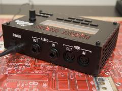
No longer a prototype... this shows the new matte black acrylic case with DIY paint-filled engraving. Quick hand-held photo... better shots to come soon.© © 2009 Jason Williams
-
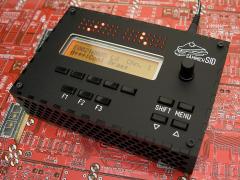
From the album: Wilba
No longer a prototype... this shows the new matte black acrylic case with DIY paint-filled engraving. Quick hand-held photo... better shots to come soon.© © 2009 Jason Williams
-

From the album: Wilba
Testing a method of paint-filling the engraving on matte black acrylic. Laser cuts through the sticky backing paper on the acrylic, which is left on while painting. Multiple coats of thinned white acrylic paint, excess is wiped with damp sponge to avoid backing paper sticking to the paint in the engraving. Looks a little messy with flecks of paint - these can be removed later when it's cured.© © 2009 Jason Williams
-
He sounds like he's from Indiana.
-
Tell him he's dreaming.
-
In theory, you could make the MIDI Out port echo messages received from the MIDI In, but this would be via the PIC's message queue and add more latency than a true MIDI Thru port, which has nearly zero latency. That would involve changes to the firmware.
-
No, you're right, Inkscape can be a huge pain in the butt in this regard, which is why I was suggesting doing it sort of manually - placing a lot of guidelines and centering things based on these, or at least validating that way. In doing so, you'll soon discover the FPD has the origin in the top left corner (legacy from originally using Zoner Draw for the panel design, which was page-coordinate based). Moving the origin in FPD might help.
-
I try not to rule anything out... like people wanting to use the PCBs in their own case design and adding more buttons, encoders, LEDs, etc. Therefore, header J2 on the control surface PCB can connect to additional DIN/DOUT modules (or shift registers on another PCB with control surface components). However, that's totally left as an exercise for the end user - they would have to design a compatible case, make it themselves, do all the extra wiring, deal with the now sub-optimal PSU/heatsinks placement (assuming you extend to the right), deal with the "optimized" long male header/female header connection between the PCBs (which suits "plug-in" but doesn't suit ribbon cable/IDC connectors), etc. In short, sammichSID is not designed to be extended, and it's a lot of work, more work than just buying an MB-6582 base PCB and building your own custom control surface.
-

From the album: Wilba
© © 2009 Jason Williams
-

From the album: Wilba
© © 2009 Jason Williams
-
You already have. :) I could probably come up with other suggestions, but if it's not too inconvenient, try a new optocoupler. But buy five just in case... and check mercilessly for shorts between ANY pins, and voltage test before you insert it!
-
If you want to reduce current to LCD backlight LEDs to ~20mA, replace R4 with larger value resistor, such as 81K and turn brightness pot to minimum.
-
That is a massive project! I can see how it would be hard to make the connection between such a big idea and the modules required to make it. For example, the number of encoders you would need far exceeds what one Core module can handle, so you will need to chain multiple Core modules, but should that be one per strip, or split it up in terms of sections of the strip, in groups of 8? I'm not sure what's better. Take the motorized faders for example... they might be best handled in groups of 8 from one Core. So perhaps one Core connects to 8 "sections" of strips, each "section" having 1 fader, X encoders, Y switches and Z LEDs. As a first MIDIbox project, it's probably too big, because you haven't learned from some experience what is possible. Perhaps you should start with something smaller, like a MIDIbox 64E or MIDIbox LC.... get some experience constructing a control surface and making changes to the code to suit your tastes. Then when you "design" your big one, you'll know what's possible and also can optimize things - perhaps you can find a way to use less controls per strip and reduce complexity, space and cost.
-
Normally you would ask permission to sell a finished MIDIbox, and then it's preferred that it is sold in the Fleamarket forum. However, this is an unfinished MIDIbox and would still require some DIY. I don't think "the rules" should stop people selling parts like this, even if the modules are already soldered. It's a one-off sale, not a profiteering enterprise, and I hope you get back the cost of that panel! BTW the listing says "Posts Worldwide" but the description says you're limiting to UK, USA and Western Europe.
-
The usual suspect is a faulty optocoupler (6N138). Perhaps this is not installed, or there are bad joints there. i.e. The PIC sends the upload requests, therefore "MIDI Out" is working. In the normal case, it would receive the upload packets and reply with acknowledgement messages. If the PICs don't receive the packet, then they don't reply. Therefore, the most likely problem is a fault in receiving MIDI, which is probably the optocoupler or something else related to it, the resistors connected to the optocoupler. You might want to check the following components are correct and have good joints and connectivity: D1 (check orientation!), R5, R11 (near optocoupler), R6_CORE1, R6_CORE2, R6_CORE3, R6_CORE4 (under PICs). Refer to this, part labels on PCB will be obscured: http://www.mb6582.org/plans/MB-6582_Base_PCB_Color.pdf
-
I know someone in AU who needs these (and I don't have enough to spare). So I'll take em (back). Do you have more parts you don't need? PM me.
-
Don't feel too bad about it, Twin-x... the only really important things lost were my incredibly interesting blog posts :bye:
-
If you use these displays, you will probably need to use less current than a normal LED array backlight LCD.... I recommend replacing the R4 resistor with 80K, thus limiting the current to around 25mA. Ideally, insert an 80K in series with R4's 1K, so you can short out the 80K later if you want to switch LCDs.
-
There are quality differences, more to do with the LCD type than manufacturers etc. i.e. "FSTN" is better than "STN", and LED array backlight is brighter overall than edge lit. If you like white on black (or perhaps green on black) then consider the Optrex STEP LCDs... these have the best contrast and are quite bright... Also I believe they do not draw as much current as your typical yellow-green LED backlight LCD. http://www.optrex.com/products/partdetail.asp?PartNumber=C-51847NFQJ-LW-AAN http://www.optrex.com/products/partdetail.asp?PartNumber=C-51847NFQJ-LG-ACN But they're relatively expensive compared to what you can find on eBay etc. I also like the red on black Orient LCD: http://character-lcd-lcds.shopeio.com/inventory/details.asp?id=1287&cat=Lcds&sub=Character%20Lcd
-
A very audible hum could be because the PSU is unable to deliver enough current. Is the hum present when there is only two SIDs installed? If the hum is gone, then the problem is too much load on the PSU, and the PSU can't deliver enough voltage to the regulators. Some PSUs cause the hum just from being noisy.... other times it's maybe an issue with the PCB, it's hard to say... you might try a test with a temporary power supply, such as 9V AC (or 12V DC) walwart and regulated 5V DC walwart... i.e. some good, new walwarts, to compare. Or some other good power supply you might have for other projects. The passive mixer is a passive mixer - you can't get less attenuation without reducing the resistors, which causes other problems. AFAIK an active mixer is just a passive mixer with op amp stages afterwards to amplify the signal level loss from the resistors. You could build an op amp stage but good ones require bipolar PSU inside the case.
-
Nice work strophlex! Where did you get those bicolor LEDs? They look greener than the ones I used on mine. Very nice.