TwoCubed
-
Posts
11 -
Joined
-
Last visited
Content Type
Profiles
Forums
Blogs
Gallery
Everything posted by TwoCubed
-
I don't know how the bankstick PCB looks like. I'm guessing it is made for 8 ICs to fit. If that's the case just mount the sockets for the ICS, solder them on and stuff them... Just refer to the diagram somewhere on ucapps, it's pretty straight forward.
-
I'm sorry for your loss but that cracks me the hell up! 'We threw the keyboard away, figured you didn't need it' <-- this is gold right here
-
Haha, I totally appreciate the comment! But I actually figured that one out myself ;) Nice to point that out though because there was a time where I didn't know what the hell I was doing. That robot I was talking about, I killed it over and over because my soldering skills were complete crap back then and I didn't really know what the hell I was doing. I'm just glad I never really fried the µC. EDIT: I got the LCD up and running but I actually did have to add a 75 Ohm resistor. So I spliced open the ribbon cable and just soldered it in between. Works out nicely! (Don't mind the temporary cables everywhere, I'll sort that mess out soon :rolleyes: )
-
Hey, thanks for the quick replies! I have indeed yet to build the modifications for the original c64 psu because Reichelt sent me the wrong caps for some reason. I will take new measurements as soon as that is done. I will probably try it first with the resistor and take it out when it's too dark. Oh and by "much higher values" I meant higher than the 3.4v. I measured 5v at 200something mA. Thanks for giving me a better feeling about this :)
-
Hi there! So I have finally gotten around to start building the first modules of the midibox sid v2. I have read a lot about the project and have gained much knowledge about it. I'd still consider me an absolute newbie when it comes to electronics despite having built some (more or less working) robot vehicle though. I have acquired the following LCD from Reichelt. It sports a white LED for the backlight. According to the datasheet, a white LED takes a supply voltage of 3.4-3.5v and a supply current of 20-25mA. Do I have to add a resistor at pin 15 or 16 of the LCD module or will the pot on the core module be able to regulate it? I'm just concerned because I measured much higher values coming from the corresponding pins on the core module. Should I need said resistor, my handy little smartphone app says I need a 75 Ohm. Is this correct? I searched the forum quite a bit before posting but I could only find similar problems related to the MB-6582 suggesting to add a 74k resistor in series somewhere on the core module itself. I'm building a modular mbsid though. I hope someone here can help me out because I really don't want to burn the lcd. Cheers!
-
I finished it :) I think it came out pretty good actually. click
-
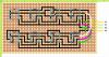
Yeah, there's not much space for that diagonal trace, but I'll try it anyway. I want to make it look somewhat like this: If I can't get it right, I'll just use some isolated wire.
-
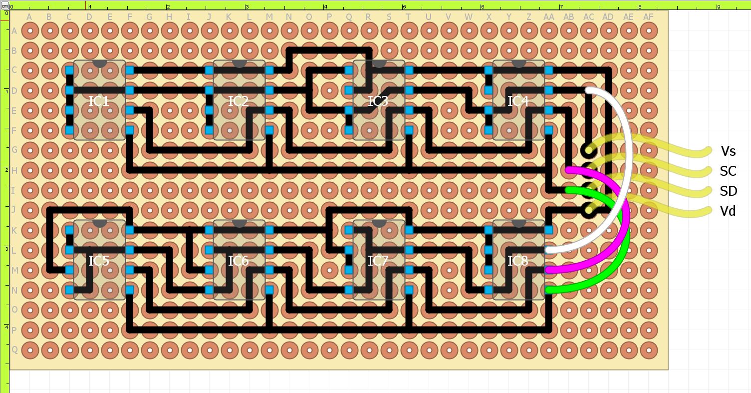
Hi there! If anybody still is interested, I have made a layout for a perforated board with solderpads. I have no idea if this will work, I just made this while I'm waiting for my shipment to arrive ;) I made this with a program called DIYLC 3.7.0 Beta. You might want to flip the image vertically for soldering. If anyone sees any mistakes, please let me know. I'm really pretty much new to this and have limited time for private projects due to being in the final phase of my studies :(
-
I wouldn't mind at all... it's just that it'd cost me over €200,-... I think I could get away with something about €30,- and it'd be a liiitle bit more "DIY" ;) Also, I found the conversion button, but just after I configured my SolidWorks for the use of inches :D
-
Yes exactly, I opened the front panel design in front panel express. How do I find out the spaces between holes and such? Is it possible to import the design file into some CAD-Program? I have access to SolidWorks and Solid Edge. I just want to be able to fully dimension this panel, so I can pass it on to the lab guy at uni: Front Panel Perhaps someone has a CAD file he or she could provide me with? EDIT: Ok, I found out how to allocate the coordinates and radius of the elements... but damn, that's some tedious work (it doesn't help that most measurements are in imperial units and some in metric units ;) ). I will make a CAD file of it though. If anyone is interested in it I'd post it here as a .step or .sat file (if I'm allowed to)
-
Hey there! I have started gathering massive amounts of information on building a nice midibox sid myself. So far I have gathered enough information to start buying the necessary parts. Only problem I seem to have is the dimensions of the frontplate for the complete control surface. I have the frontplate design and the software to be able to view it, but I was expecting something more CAD-like with the ability to view the dimensions between holes and such. Am I just missing an option here? I would like to make use of the CNC drill at our uni as it would massively reduce costs for the frontplate (it would cost me nothing but the plate itself). Can anyone help me out on this? I don't think I'm quite ready to handle my own frontplate design just yet... That's for the future :) I gladly appreciate any help! Shane