

Sauraen
-
Posts
460 -
Joined
-
Last visited
-
Days Won
26
Content Type
Profiles
Forums
Blogs
Gallery
Image Comments posted by Sauraen
-
-
On 2/2/2017 at 3:16 AM, latigid on said:
Very pretty! May I ask what current you're driving through the LEDs? Do you experience any voltage sag/droop at the 595 anode outs? The story apparently goes, that if you're drawing more than 5-6mA (continuous) through a 595 output pin, the source voltage will decrease. http://electronics.stackexchange.com/questions/77841/how-much-current-can-my-74hc595-handle-on-each-output-pin
While keeping in the MIDIbox paradigm of ordinary shift register chips, one thought is to add PNP BJTs as "current sources" (moreso voltage sources due to constant current sinks on the cathodes). Any thoughts on this?
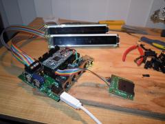
The current-limiting resistors are 220 ohms, so roughly (5 - 2.1) / 220 = 13mA. This was the third MIDIbox I built with 595's directly driving LEDs (at least the anodes), and I haven't had any trouble with it, so I never looked into it. This picture is actually a year old, I just put it up because I've gotten some interest in other people building these Genesis synths.
-
Slick!
-
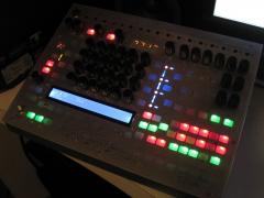
Thanks! They're custom 3D printed--the whole order cost $20 including shipping.Those illuminated switch looks really good!!I guess they are custom made? (laser cut?)
Note "improperly configured" in the title. :smile:the 7 digit display seems to use alien numbers :smile: -
Ha ha, thanks!
-
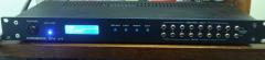
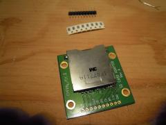
Where did you get this?
-
Where did you get this SD card adapter board? Is it a MIDIbox thing or a regular commercial product?
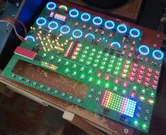
MIDIbox Quad Genesis Front Panel (MBQG_FP) PCB: Most LEDs On
in MIDIbox Gallery
7Posted
Oh, all three front panels have used row drivers; in MIDIbox ASIDITY it was a bunch of TO220 NMOSFETS, in MIDIbox FM V2.0 / V2.1 it was a Darlington array, and in this one it's eight TO92 NMOSFETS, they're right next to the orange LEDs in teh middle. Obviously the shift register pins can't sink >1 amp!
But I don't quite understand the issue--MIDIboxes have been using BLMs with this scheme for 15 years. And in fact, since only one row is on at a time, having 8 or 16 rows from each pin of the shift register is just the same as having each shift register pin drive one single LED by itself. That's what the DOUT module is specifically designed for.
You're right about PWM, but I don't use dimming on any of these panels. :) I don't find that it's terribly useful to convey information to the user.