

Sauraen
-
Posts
460 -
Joined
-
Last visited
-
Days Won
26
Content Type
Profiles
Forums
Blogs
Gallery
Everything posted by Sauraen
-
Thanks TK, it was a null pointer. :) I was not expecting such a small processor to have such a sophisticated hangup detection routine!
-
Thank you for the fast fix! In the User Manual, this item is called ".pins", not ".pos". However, I see in $MIOS32_PATH/include/mios32_enc.h that the appropriate variable is in fact mios32_enc_config_t.cfg.pos. Is this what you changed the handling for? If so, does the NGC parser simply read the first of the two pins specified and set that value into mios32_enc_config_t.cfg.pos, so we should simply be able to write our configuration files with ".pins=1:0", etc., with no further changes?
-
Hi TK, In the manual configuration for encoders, I see you have only four options for connecting encoders to a DIN shift register: 0:1, 2:3, 4:5, and 6:7. It says "If you notice that the encoder increments in the wrong direction, the pins have to be swapped at the hardware side!" Is there any chance you could also include 1:0, 3:2, 5:4, and 7:6 as allowable modes? I'm laying out a board for a front panel that encoders will be permanently mounted in, and I don't want to power it up and find out half the encoders turn in the wrong direction, because I can't swap the wires on the hardware at that point! (Plus it makes it easier to lay out if I can swap the order arbitrarily.) I'm sure you could figure this out quite easily, but this is a quick way to swap bits 1 and 0, 3 and 2, 5 and 4, 7 and 6. It would seem to me to be as easy as making a copy of the input data byte from the shift register, modifying the copy as follows, and then reading from either the original or the copy according to the configuration line. data = ((data & 0x55) << 1) | ((data & 0xAA) >> 1); //or in assembler, assuming data is in r1 mov r2,r1 andi r2, 0x55 rol r2 andi r1, 0xAA ror r1 or r1,r2 Thanks, Sauraen
-
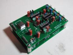
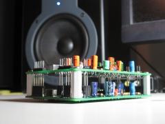
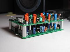
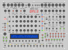
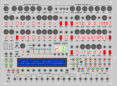
Here's some pictures of my OPL3 modules: If you're only building one OPL3 module, no modifications are necessary. If you want to build two, and you want them to be stacked like this, this is what I did: The CS/WR pin on each OPL3 has to be independent (not connected between the boards, you can see it very well sticking out on the first picture). This is so that the core can send different data to each chip (obviously)! All the other digital data and power supply pins are connected together for the two boards. If you want the outputs to mix (channel 1 of each mixes, channel 2, etc.), change R17/R19/R21/R23 to 10k and R16/R18/R20/R22 to 100k, and connect the outputs together (1 to 1, 2 to 2, etc., like all the digital pins). Then make a circuit on veroboard with an op-amp for each channel (you can use one more TL074 to cover all four), in inverting amplifier configuration with a 10k feedback resistor (for unity gain mixing). After that put a final AC coupling capacitor (10 uF electrolytic or non-polar), bias resistor to ground (10k), and series current limiting resistor (220 ohms) to the output jack.
-
MIDIbox FM V2.0 Prototype: OPL3 modules completed!
Sauraen posted a gallery image in MIDIbox Gallery
From the album: MIDIbox FM V2.0 Prototype
Didn't know this was going to be a sammich build, eh? :smile: -
MIDIbox FM V2.0 Prototype: OPL3 modules completed!
Sauraen posted a gallery image in MIDIbox Gallery
From the album: MIDIbox FM V2.0 Prototype
Didn't know this was going to be a sammich build, eh? :smile: -
MIDIbox FM V2.0 Prototype: OPL3 modules completed!
Sauraen posted a gallery image in MIDIbox Gallery
From the album: MIDIbox FM V2.0 Prototype
Didn't know this was going to be a sammich build, eh? :smile: -
MIDIbox FM V2.0 Prototype: Really Two OPL3 Modules!
Sauraen posted a gallery image in MIDIbox Gallery
From the album: MIDIbox FM V2.0 Prototype
It's really happening! :D Glorious 36-voice polyphony (or, alternately, 36-voice detuned unison)! -
I'm working on inter-LPC17-core communication via MBNET. It's going pretty well, I have MIDI messages generated from front panel events detected by one core being sent to and received by another core. However, for this other core, it works fine for only about 23 seconds. During that time, it connects to MIOSStudio, I can upload new code, etc., and see it telling me in debugging messages that it's receiving correct MBNET data from the other core. Then, after about that much time, when it receives another MBNET event, it instantly stops responding to MBNET as well as MIOSStudio (it labels it as "MIOS32*" in the menu, and it won't connect), and the light on the LPCXPRESSO board blinks with a frequency of about 2 Hz (no PWM, actual blinking). When I power-cycle the core it works for another 23 seconds or so. If I don't send any MBNET data, it just sits there working fine (and responding to MIOSStudio), but if I send any MBNET data after 23 seconds after turning it on, it immediately hangs up like this again. It's something about my code, but not something obvious (i.e. I didn't program the light to flash like that!). When it's running the MBNET test program, it continues to work for at least a few minutes, continually receiving MBNET data and showing it via MIOSStudio. However, to make the code for this core, I just copied-and-pasted the code from the other (sending) core, and modified it in seemingly non-essential ways. It looks like it's hanging up after completing the scan of MBNET nodes, because that's about as much time as it takes to scan the nodes when running the test program; but the fact that it works during the scan, then fails at the end, and fails in such a way that it disables USB and starts the status light flashing is a complete puzzle to me! This has got to have been programmed as a "crash state routine" for the CPU to enter under certain conditions, but I don't know how I got it into that state.
-
If when you say stereo mixing, you mean the assigning of each pair of operators to output channels 1,2,3,4, then yes, I plan to have that parameter, like every other OPL3 parameter, MIDI-controllable via CCs. I'm thinking something like this: CC 10, Pan position, will switch channels 1 and 2 to emulate a panpot (i.e. 0-31 only channel 1, 32-95 channels 1 and 2, 96-127 only channel 2), and then some other CC (27 or something) will have its most significant three bits DISABLE channel 4, channel 3, and whatever-CC-10-says-channels-1-and-2-are-doing (so the default value of 0 has everything enabled). This way you can just twiddle the pan knob in your DAW to move channels around that are standard, outputting only to channels 1 and 2; and you can send that other CC to set up the channel in detail if you want something different. I also kind of want AOUT support, so I can build a digitally controlled filter; but that'll be a later feature. I'm thinking 8 global modulation destinations corresponding to the 8 AOUT channels; a menu option to put them temporarily on the display as the 8 softkeys; and then you assign modulators to them like you would OPL3 parameters. Does Adlib Tracker 2 support two OPL3s? :P
-
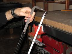
If the idea of scoring a groove in your LPC1769 board with a utility knife seems tedious, guess what... you're right! It is! Here's another way that I'm sure is just as legitimate! :P
-
Another totally legitimate way to separate the LPC17 target from programmer
Sauraen posted a gallery image in MIDIbox Gallery
From the album: MIDIbox FM V2.0 Prototype
So much for utility knives! This took less than a minute. :smile: -
Thanks Hawkeye! :)
-
I don't quite know what you're talking about, playing notes into an OPL3 with a computer keyboard. And there's 16 channels in MIDI versus 18 in an OPL3.
-
Any classic video game music fans out there? Or if you prefer, in higher quality and mp3 320 download: https://soundcloud.com/sauraen/ocarina-of-time-end-credits REAPER was a GREAT idea! Perfectly stable even with 11 GB of sound libraries loaded into RAM!
-
So if I am planning a build (MBFM V2.0) that requires a lot of encoders (~40), you would recommend that I get 10 74HC165s and hook them up directly, not in a matrix? Personally I would just modify the firmware, but since I want this to be compatible for everyone, that's probably not a good idea. :) It would take somewhat longer to select multiple rows and shift in data from each than to shift in data from one much longer DIN chain, but would it be that different? And wouldn't it be easier on the hardware side to work with a matrix of encoders than a dedicated shift register for every four encoders?
-
Hi TK, Does the current MBNG firmware allow connecting encoders in the DIN_MATRIX? In the documentation, I see how to configure individual buttons from the matrix as separate, independent buttons, but I don't see anything about encoders. For instance, something like: DIN_MATRIX n=1 rows=8 inverted=1 \ sr_dout_sel1=1 sr_dout_sel2=0 \ sr_din1=1 sr_din2=2 sr_din3=3 sr_din4=4 \ button_emu_id_offset=1001 ENC n=1 buttons=1001:1002 type=detented1 ENC n=2 buttons=1003:1004 type=detented1 ...
-
Then what is the demo sample from http://ucapps.de/midibox_fm.html labeled "The 16 MIDIbox FM drumset presets"? I guess "drumset preset" isn't the same thing as "drum sequence preset", maybe they're done with an external sequencer. Well anyway, MIDIbox SID contains a small internal sequencer, so why not!
-
@Shuriken @niklasni1 Especially when learning to use a sound architecture (e.g. FM synthesis) for the first time, I would very much want to be able to see ALL of the options at my disposal. "FM is not like an analog synth where parameters make sense, you will have more chance of having a nice patch by using the random patch generator"--why bother trying to control anything then? :smile: (And that's only true because TK did such a good job with the random patch generator, making it not completely random!) Also, since this is basically a test build for the MBFM V2.0 driver and application, the easiest way to make sure that everything is working properly and as expected is to have everything on the front panel. Finally, I happen to already have a case that this front panel would be mounted on, so the size is fixed for me, and there's no point in having empty space where I could put a knob. @Imp The chorus and filter are fully-analog (not CV) modules I'm working on and going to connect to outputs 3 and 4 of the OPL3s; the application will know nothing about them, and I don't expect anyone else to replicate them. The delay parameter will allow you to delay note data triggering a voice; when you use two voices with one delayed, detuned, and possibly stereo-separated, you can get some nice chorus/delay/flanger/etc. effects, at the cost of one button and one knob on the front panel (and a bunch of RAM used, but that's not a problem as long as everything eventually fits). As far as the sequencer, I'm not going to work on that initially, I just wanted to save space for it on the front panel. If I was going to make a dedicated sequencer, it would be much more powerful than that. AFAIK MIDIbox FM V1.4 MIDIbox SID has a drum pattern thing that is about as powerful as what I am proposing.
-
The picture is kind of enormous, but the actual front panel is sort of average-sized, I think it's 11" x 15" off the top of my head. It's to fit on a nice case from a device I got out of the trash. I guess it's enormous if you were expecting a sammich-type device! I don't like layered menus at all. I avoided the use of a bunch of buttons for less-used parameters by using a sort of menu for them: hold down the PARAM button and the display shows all those parameters, press the softkeys to turn them off and on (built-in LFOs, key scaling rate + amp, hold mode). This also is how the wave select works for both the oscillators and the software LFOs. I won't claim that having all those knobs directly available will make FM synthesis any easier--but it certainly can't make it harder than hunting through menus to edit parameters. I have an EMU ESI-4000 that's sitting completely unused on my rack, because while it's decently powerful, most of the time spent using it is navigating through the menus. I've also used the SY-99 decently extensively, and the menu-based structure is made up for by a graphical screen and the fact that the front panel would be the size of a mixing console if you had a control for every parameter of a sound! But if menus are what you like, again this is on the MBNG framework, so you can edit the interface however you want. One more change I'm making to this is that I looked up the pricing for the buttons, and ouch! I decided to go with standard tact switches and LEDs on veroboard, and have custom translucent buttons 3D printed like for my ASIDITY project. This is actually much cheaper!
-
Would this be satisfying? Also, I completely rewrote the first post to be more like a feature list.
-
From the album: MIDIbox FM V2.0 Prototype
Starting to look real legit! :smile: For each of the non-lighted buttons, you hold it down and options come up on the screen for that setting, and then you press the softkey below the option you want. For example, hold down Wave and you get the 8 waveforms as choices across the screen. Hold one button and press another is, to me, quicker than scroll through options with an encoder. If you don't have the front panel space or are not so inclined for some reason, you may build only one or two of the operator edit rows. -
You're right, assuming that most of your control inputs will be slightly adjusting an already-existing sound (or one that's playing), rather than creating a new sound from scratch. It depends on your style of using the synth: if you want to hook this up to a MBSEQ V4, press Play, and start tweaking things, absolutely; if you want to make patches and then program a complete song into your DAW or play it live with your keyboard, you're mainly going to be touching knobs to change them dramatically, not slightly. But I was thinking about it, and I didn't like one feature of the Electribe, which was jittery parameter values that required you to barely touch the knobs to get right. Detented encoders will never have that problem, and the only values here for which I would want the full speed of a non-detented encoder would be in the software modulators--none of the OPL3 parameters are high-res enough. As far as the almost-useless parameters like KSCL, the control surface configuration will be through the MBNG platform, so you can put them in a menu if you want; I don't like menus at all, so I'm going to leave them out on the front panel. :) I do like lots of controls, and part of the purpose of this build for me is to demo MIDIbox FM V2, and really, to demo the OPL3. So I want a control directly on the front panel for every OPL3 parameter. So let's say I take off all those LED displays. Do I add in a full set of encoders for all the parameters of the other two operators that may or may not be part of the current voice? Again, you can make your own build one way or the other, but what should I do? I think it would feel cluttered to include the controls for all four LFOs and two EGs, and after all those really aren't OPL3 parameters. Maybe the full controls for one of each, a button to select which one is currently mapped to the controls, plus an Assign button? There are encoders on eBay for $0.99 per 10 (plus shipping).
-
@lazerbeat: Added, thanks! I know what you mean, working with the SY99. Though that has up to 24 operators per voice... :rofl: And I will update the first post soon! @Imp: I'd love to do this, but there's no way I'm wiring all those LED displays on veroboard. That's 7 shift registers in the matrix just for selecting digits! Makes me REALLY want to do the potentiometers--SO much simpler... Unless a bunch of people want to do a bulk order for a front panel board, or I can persuade someone to let me use their CNC machine to rout a custom board, I don't think this is going to happen.
-
From the album: MIDIbox FM V2.0 Prototype
So you want rotary encoders, eh? How about a few LED displays? I'm cringing at soldering wires to all those displays by hand! There's no way I'm going to do this build unless I can figure out a cheap way to get a board made for the whole front panel. And that's 7 shift registers dedicated just to selecting the digits!
