Sauraen
-
Posts
460 -
Joined
-
Last visited
-
Days Won
26
Content Type
Profiles
Forums
Blogs
Gallery
Everything posted by Sauraen
-
Thought about it, did some searching on eBay, found encoders that were actually cheaper than potentiometers... I'm not sure now. I've used the Korg Electribe and microKorg pretty extensively, both of which use potentiometers. The former uses hard-takeover, the latter soft-takeover. I very much prefer the former. If I'm turning a knob for a parameter, I want that parameter's value to change! And I want to change it as quickly as possible to the value I have in mind, which is only possible with an absolute control method (not relative like encoders). Most of the time I'm not tweaking the sound bit by bit while the synth is playing--instead, most of the time I want the synth to be tweaking the sound bit by bit while I'm playing (via EGs, LFOs, Wavetable, or even sequenced CCs). The soft-takeover on the microKorg was a pain for me, because I would first have to turn the knob to whatever the current value was, and then turn it to the value I wanted. Smooth, yes, but delayed--what if the value is at 0 and I want it at full and the knob is at full? If it had hard takeover I could just touch the knob and it would jump to full, whereas there I have to turn it all the way down and then all the way up. Relative motion like with encoders solves the delay problem, but you still have to know what the value was in order to know how to change it quickly, you can't just turn it to what you want it. The other issue is the range of parameters. If I can take apart the encoders I get and remove the detent, they will be usable, because it will be 64/96 steps per complete turn (the maximum resolution of an OPL3 parameter is 64 steps for OP-volume). For the software-based modulators I suppose I could live with turning them four times around to go through the whole 8-bit range, though that's a bit obnoxious. However, if I can't mod the encoders without ruining them, and even if they had 24 steps, that would still be 10 complete turns to go through the range of a parameter of one of the LFOs or EG. As far as seeing the values on the knobs, I'm NOT going to fiddle with (or pay for) LED-rings. Not for 26 knobs. What do other people think? I know this is, like, one of the biggest ongoing arguments in MIDIbox-land, but would anyone else want to do a build with potentiometers?
-
Others may be more qualified than me to address this, but AFAIK the point of the MIDIbox SID lead engine is to let you use multiple voices (and/or multiple SIDs) to make one "instrument" sound, whereas on an actual C64 you would use one voice to make multiple "instruments" or sounds on an alternating basis. However, look at the Multi Engine, which will let you do 24-voice polyphony with a MB6582. You could even do multiple "instruments" being played at different times with one channel by sending a ton of CCs to set up all the parameters every time you wanted to switch instruments (possibly every beat!), if you're willing to program that into a DAW. As far as the wavetable, I refer you to the lead engine's manual: "The term "Wavetable" is used by the C64 community for a synthesis method, where the waveform and frequency of a SID voice is modulated so fast, that the resulting output sounds like a new waveform, which is originally not provided by the soundchip itself. The parameter changes are stored in a table - that's the reason for this name - the technique is not related to "wavetable synthesis", which is based on audio samples. MIDIbox SID provides a very generic wavetable sequencer, which can not only control the waveform and frequency, but any parameter which is also accessible via NRPN" It's basically a 32-step 4-destination sequencer for parameter changes. This is not the same as creating a fourth voice for the SID to play (which some trackers allow you to do).
-
That is one of the reasons I wanted to do this build! I know I can be a little long-winded sometimes :), but I talked about that a bit above. The whole idea is to be able to connect it to a DAW/sequencer and have each MIDI channel be one patch, possibly across multiple voices, and then you could program it like an OPL3 in a soundcard. One thing I didn't talk about was how it would handle 2-op versus 4-op voices. The short answer is select a voice that is the first of a pair that can be combined (i.e. 1, 3, 5, 7, 9, 11 on either OPL3), and press the 4-OP button (or throw the switch in my above drawing). Patches would be saved based on how many of each type (2/4-op) they needed. For 2-op patches, it would fill up the voices that can only be 2-op first, and then start using voices that could have been combined. I haven't built one, but AFAIK you are correct, it is not an option. MBFM 1.4 never even uses three of the two-op voices that cannot be combined or turned into percussion. Overall, you have 18-2d-3p 2-op voices, d 4-op voices (with 0 <= d <= 6), and 5p percussion voices (with 0 <= p <= 1) that are permanently attached to Bass Drum, Snare Drum, Tom-Tom, Hi-Hat, and Crash Cymbal. Since this was probably unclear, see the picture above.
-
Probably not, but I don't think that's something I can fix. When I first built it and heard the ridiculous amount of noise, since the motherboard I got was advertised as having a 108 dB signal-to-noise ratio for its integrated audio card, I complained to the manufacturer. In performing the tests they asked me to (and some they didn't), I ended up with the motherboard by itself on my desk just hooked into the PSU, mouse, keyboard, screen, and speakers, with no drives or other peripherals. As soon as I plugged the power cord into the PSU--even before turning on the master switch on the PSU--noise started coming out of the speakers. Turning on said switch caused a burst of noise and then it died down to previous levels; turning on the motherboard produced more noise, and even scrolling through the BIOS screens would produce a "click" of audible noise every time it refreshed the screen. I tried this all with a different PSU but got identical results. The speakers are connected to the same surge protector as the computer, but almost everything else (e.g. mixer) is connected to a different surge protector. However, if I connect a dynamic mic directly to the mic in port on the computer (so there's no question of a separate device that's also plugged into the wall) and hit Record on Audacity, all the noise gets digitally recorded along with the actual sound going into the mic.
-
Science! Just connecting a wire from the computer's ground to my mixer's ground, with no other wires between them, makes hard drive data noises come out of the speakers (connected to the mixer). I found a ferrite ring in a drawer in my electronics stuff, put 16 turns around (through) it, and connected that between the two grounds. Result: same noise. :( Measuring with my portable (and therefore ground-isolated!) scope, the noise between the mixer ground and the computer ground when they are not connected is around 50 mV P-P, and spikes to 100 mV when the computer is loading a large program. Oviously audible! I also tried some antenna coils--with ferrite cores--from the same drawer, and the noise comes right through. However, I then tried a small transformer (from a electronics kit radio), and the noise does not appear when I connect the two grounds through it, even though there is 200 ohms resistance between the two. The scope shows the full noise across it, and I don't hear any; but due to the non-infinite resistance between the two ends of that transformer coil, they must be held at the same potential. So it looks like I found what I'm looking for--and I had it all along! I will buy a cheap USB audio interface and wire the transformer in series with the ground connection and power the interface from an external linear supply on the audio side, and see what happens.
-
I can power any USB audio interface from the same linear 5v power supply I built for the optical to RCA converter, so getting 5V to it is not the problem. The problem is getting the audio ground at the same average potential as the USB ground from the computer without letting noise on the latter propagate to the former. As far as I know, setting up a filter like the one above will get the +5 rail to be smoothed relative to the ground rail, but it will not smooth out voltage fluctuations in the ground potential itself. Or will it if I put the black wire through an inductor as well? If you're sure a DC-DC converter has both +5 and GND rails decoupled from the source, I can order one from my "local" electronics supplier (Mouser, Digikey, etc.) :smile:.As a matter of fact there's one that might work from Mouser for $3.30. After a little research it looks like the "isolated" keyword on a DC-DC converter means -Vin is not connected to -Vout, which is what I'm looking for. Still one question though: Because the USB data wires have to go across this isolation gap to the ADC chip, I can't have the two grounds floating with respect to each other--they need to be at the same potential. But hooking a wire between the two grounds would destroy the whole point. So what should I connect between them? A very-high-resistance resistor (~1Meg) in parallel with a very-large capacitor (~2200 uF)?
-
The main problem is the computer's ground is extremely noisy, so it doesn't matter how expensive an interface I get, as long as it has the USB ground connected to audio ground, the audio will be horrible. As a matter of fact, if I connect a single wire from the computer's ground to my mixer's ground, immediately I can hear hard drive data coming out the speakers. As far as the audio side, I only need two channels 48khz 16 bit, nothing fancy. However I did find something that might be useful: a USB ground isolator: http://www.ebay.com/itm/HiFimeDIY-USB-Isolator-ADUM4160-5KV-3KV-signal-voltage-isolation-DC-DC-convert-/141087228001?pt=LH_DefaultDomain_0&hash=item20d9744061 With this plus a cheap audio interface (e.g. http://www.ebay.com/itm/New-Behringer-U-Control-UCA-202-USB-Audio-Interface-Adapter-in-BOX-UCA202-Hot-/290985992006?pt=US_Computer_Recording_Interfaces&hash=item43c01ddf46 ), do you think this will solve the problem?
-
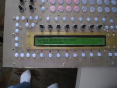
LCDs working! Now to assemble the first modulation: MIDI from SEQ core, parameter changes from FP core, routed to SID core to write to OPL3!
-
Sauraen and Oikanys make what they hope will be the world's most powerful SID-based synthesizer. MORE CONTROL!
-
-
From the album: MIDIbox ASIDITY
Shouldn't have been that hard! (Bad connections in cheap IDC connector) -
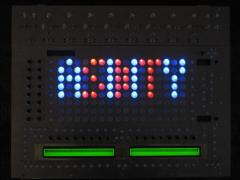
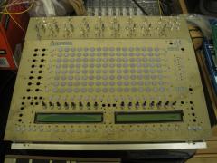
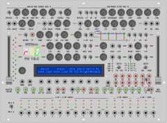
Current front panel mockup design: (Please ignore the floating toggle switches in the lower right hand corner... this was a quick job and I didn't notice until after uploading...) The indications on the LCD represent: Channel 12; 6 voices assigned to it, patch uses 0 4-op voices and 2 2-op voices; 5 voices free, i.e. 1 4-op voice and 3 2-op voices; current polyphony on this channel 2 (two notes playing); Bank 0, Patch 102, Name: BrightRhodes2 I was going to just put in drum trigger buttons (you would only have one row if you put in only one OPL3), but then I figured I'd leave room on the front panel for a small fractal drum sequencer. The 18-position button array at the bottom (not all those LEDs are necessary) would be perfect for this: each measure actually stores 17 steps, and the 17th step from the last measure is played at the same time as the 1st step from this measure. The measures are played in the order 1-2-1-4-1-2-1-8, so you only have to store and edit 4 measures and you get an 8-bar pattern. The 17th step of bar 8 could be a crash cymbal, for instance, and then it would only play it at the beginning of the whole loop, not every time you played measure 1. Anyway, this is not going to be something I'm going to work on at first! @Thomasch: 1. I was planning to have all the "mappable" controls (see panel: LFO1, LFO2, EG6, WT (Wavetable, i.e. 16-step parameter sequencer), VEL (velocity), and MOD (CC1, modwheel)) work like this. Hold down button of the modulator (e.g. VEL button) and turn the knob that is the parameter you want the modulator to affect (e.g. volume). Center of knob means zero effect, all the way right means full range positive sweep, all the way right means full range negative sweep. The value of the parameter (e.g. volume) that you put in while NOT holding the VEL button is the "center" value that you will hear when the modulator is in the middle (e.g. velocity 64 or LFO centered). So you basically have a control for the center of the modulation and then a control for amount around center. Each modulator can have as many targets as you want (though keep in mind the stuff in my first post about slowing down the framerate). 2. I like your filter idea (note the "Multimode Filter" section on the top of the panel), but it can't be polyphonic, since the OPL3 does not have it built in and it only has 4 audio outputs. In my build this will just be hooked up to Output 4 ("Bus 2"), but this would be up to each individual person--it's all analog, not driven by software at all. I'm also throwing into mine the guts of a cheap 80s guitar chorus pedal, hence the "Analog BBD Chorus" section, but again, not standard. 3. I didn't think of the switchable thing, but I'll make a softkey available when you're holding down the LFOx button to switch it. Why do you want more envelopes, though? I was going to include one per voice (per two operators, so two for a 4-op voice) like in MBFM 1.4. If you want authentic period sounds, the 4-bit parameters come with the territory! (And keep in mind that the external volume parameter is only 6-bit whereas the internal EGs can modulate the volume at a much finer resolution, so software EGs will give you improved timing accuracy at the cost of worse output resolution.) 4. I'm going to build it on the MIDIbox NG framework--the synth engine will simply be more parameters that you can put into your configuration files to have your front panel control. Personally I want to do a build with nearly all analog potentiometers, and I don't want to fiddle with LED rings; but if that's what you want, go right ahead! Everywhere I have a toggle switch could be replaced by two buttons-with-LEDs, and of course pots with encoders. 5. I will add a menu option of whether you want it to respond to only 7-bit bank change messages on CC0, only 7-bit messages on CC32, or 14-bit messages across both. I will not attach any other parameter to either CC. When you save a patch, it'll be some .mbfm file on the SD card, and you can tell it when saving what bank number and patch number to make it (they don't have to be contiguous).
-
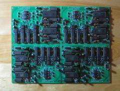
From the album: MIDIbox FM V2.0 Prototype
Sorry for the bad drawings of the knobs and switches... -
Glad to see some interest! :D So: all the controls for one operator; four buttons with LEDs to select between operators (if it's set to be a 2-op voice, only the first two will work); all the controls for that voice; 18 buttons with LEDs to select between voices, and two buttons with LEDs to select between OPL3s (if you have two). Do you want the controls for the software-implemented modulation, i.e. the two LFOs, EG, Wavetable, velocity response, and modwheel response for each voice, to also be on the surface, or in menus? (I'm leaning towards the former; that's not that many knobs, and the latter three are just a single button each to select the destination that the parameter modulates.) This is how I was thinking of doing the patches. Hold down MIDI button and press one of the voice buttons 1-16 (minus 10 which is permanently mapped to drums) to select a MIDI channel. MIDI button's light turns on as well as that voice button's light. Hold down SELECT button and press voice buttons to assign those voices to this MIDI channel. Now press FM button to switch back to voice editing mode. Select one of the voices you had assigned to that MIDI channel and edit its parameters until you get the patch you want. Now, if you want all of the voices assigned to this channel to play that patch in polyphony, select each of them, hold the DUPL button, and select the voice that has the patch you made. This will do two things: lock the parameters of those voices to match the parameters of the one you made (so when you edit that voice, whether manually or through CCs, it updates all of them); and tell the polyphony engine to assign any incoming polyphony on that MIDI channel across all those duplicated voices. However, if you want multiple voices (e.g. two) to sound when one note is played (e.g. for a stereo effect, or let's say 3 (or 36!) voices detuned for a unison effect), select the second voice, hold the LINK button, and select the first voice. Now edit any parameters of the second voice that you want to be different from the first voice (e.g. output assignment, tuning). These parameters will be saved per voice, but any parameters of the second voice that you haven't touched will be linked to the first voice (e.g. volume), so if you edit the first one it will update those for the second one. The polyphony engine will activate all linked voices at once. When you save a patch, it will save it as needing as many linked voices as you have set up, but it will ignore duplicated voices. So later, you can load that patch into a channel that has been assigned a different number of voices, and it will automatically fill them up with duplicates of the saved voice for polyphony. I think an example is in order. Let's say you want to make a pad that sweeps smoothly from side to side through the stereo spectrum. Since the OPL3 audio outputs are binary (not volume-leveled), you need to use two voices, one set to left channel and one to right, and change their volumes so one increases as the other decreases. Pick a MIDI channel and assign two arbitrary voices to it, let's say voices 13 and 14 because we happen not to need 4-operator voices for this patch. Select voice 13 and set up the pad, assigning it to L channel and hooking one of the software LFOs to the second operator's volume, with a starting phase of 0. Select voice 14, hold LINK, press voice 13 button, release LINK. Assign the voice to R channel and change the phase of the LFO to 180. Press SAVE, make up a name, it will say on the screen that this patch uses two 2-op voices. Now you want to play this patch with 18-voice polyphony across both your OPL3s. Select a MIDI channel and assign all 36 voices to it from both chips. Press LOAD and select your patch. Your patch will now be loaded into all 36 voices--or rather, the first voice of your patch will be loaded into the odd-numbered ones and all will be DUPL'd to voice 1, and the second voice of your patch will be loaded into the even-numbered ones and all DUPL'd to voice 2. Voice 2 will be LINKed to voice 1. As far as MIDI CCs, this could be accomplished as follows. I'll set up some CC with a large value (over 100) that means "assign the voice whose number is the data to the given MIDI channel". So send a bunch of those CCs with the channel you want and data values 1-36. Then simply send a program change message for whatever index your patch was saved as, and it will do what I described above when you select your patch. How does this sound?
-
My desktop has a noise problem. I don't know whether it's the power supply or the motherboard or what, but if I play audio directly from its integrated audio card the signal-to-noise ratio is about 1! (the noise is as loud as the music) I solved this problem by buying a SPDIF optical (TOSlink) to RCA converter and hooking it to the optical audio out on the motherboard, so the grounds of the two are not connected. (I also had to build a linear power supply for the converter, since its $2.00 switching wall-wart added a ground hum.) The overall latency is less than 10ms and the audio is crystal clear, so I'm happy. But now I want to record audio into the computer! If I do it directly (whether mic in or line in), there is again a huge amount of noise. So I need some sort of interface box that takes at least one audio input--that part doesn't have to be fancy, though I guess stereo would be nice--powered by an external linear power supply, and output a USB-audio-device signal of that incoming audio, with the audio input completely electrically decoupled from the USB side (not sharing a ground). Any recommendations?
-
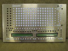
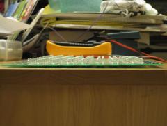
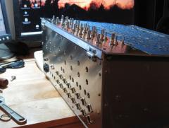
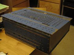
[image: MIDIbox FM V2.0 Prototype, testing temperament system with Goldberg Variations] Since I've now developed and partly tested a driver for the OPL3 module for the LPC17 core (see ), I've been thinking about what the full next-gen MIDIbox FM will look like. [Edit: Well, uhh, there's a picture above...] I have some parts for a new build, and I've been thinking of taking a hiatus from the above project to develop a prototype MBFM 2.0, with a complete module driver, and hopefully, with an application layer that can be modified easily into an official release. Here's what I'm currently planning; please post suggestions or feature requests! Up to two OPL3 modules controlled by parallel interface. Each OPL3 module provides all of the following: 12 2-op voices, each pair of which can be combined into one 4-op voice, for up to six 4-op voices; plus 3 2-op voices which can't be combined; plus 3 2-op voices which can be turned as a whole into 5 percussion voices. This means that, from each module, you can have up to 18-voice polyphony of 2-op voices, up to 6-voice polyphony of 4-op voices plus up to 6-voice polyphony of 2-op voices, or either of the above minus three 2-op voices plus drums. You may use one or two OPL3 modules and set up any of the voices arbitrarily (within the hardware limits of the chip). The parallel interface will have D7:D0 of the OPL3 module connected to J10 of the LPC17 module, /RS of the OPL3 module connected to J19:RC1 or RC2 (whichever is not otherwise in use), and the other OPL3 pins (A0, A1, /CS for OPL3 A, and /CS for OPL3 B) connected to J28. I expect one full register write operation to take around 15 us. Front panel using MBNG framework. If you don't like what buttons/knobs I'm putting on the front panel of mine, make your own! All synth engine parameters (both OPL3 parameters and things like modulator connections) will be MBNG commands that you can write into your configuration file. The default config file will also have all the parameters hooked up to incoming CCs, and you can modify this as well of course. In addition to just modifying all the parameters of the OPL3, sophisticated core-based modulation like in MBFM 1.4 (but slightly more powerful). Each 2-op voice gets: one 6-step (ADBSSR) EG two LFOs, with frequency, delay, and waveshape controls; option for whether the frequency is a function of the tempo, or of the system time 32-step "wavetable" parameter sequencer Velocity modulator Mod Wheel modulator CC2/Variation modulator For a 4-op voice, you get doubles of the first three of these (2 EGs, 4 LFOs, and 2 Wavetables). Doubling the last three wouldn't make any sense! Each of these modulators has an Assign button. Hold down that button and tweak any knob on the front panel to make that modulator affect the value of that knob. The value that the parameter was set to before being assigned (or whatever you change it to while not holding the Assign button) is the "middle" value of the parameter, what it will use when the modulator is halfway through its range. The amount by which you adjust the knob, in either direction, while holding down Assign is the depth of the modulation, the range around that middle value. You can assign any modulator to any number of targets, including parameters of the same modulator, with independent depths. Edit: However, each voice supports a maximum of 16 of these modulation connections due to RAM consumption. Currently not sure whether my synth engine is going to be able to handle 32 connections for a 4-op voice, or if it'll be 16 connections there too. Still don't think you're ever going to run out, consider other synths give you 4 per voice or 8 for the whole machine. Equal temperament or custom temperament system editable straight from front panel. Arbitrary, semi-dynamic voice allocation based on MIDI channels. Select a MIDI channel and assign any number of voices to it. Load a patch and it will fill out those voices in polyphony as well as possible. One voice that is a polyphonic "copy" of another will be linked to it with a DUPL button (automatically done on loading the patch). Also available is a LINK button that will cause the two voices to be sounded simultaneously, with any parameters that you modify of the LINKed voice remaining independent from the first, but changes to all others on the first affecting both. A patch may consist of any configuration of LINKed voices, not just two. CC 0 / CC 32 bank change messages and Program change messages will be supported properly (not mapped to any other parameters). Save a patch or a complete state of the synth to SD card (no BankSticks). Small fractal drum sequencer (later feature). 12(10) tracks, 16(17) steps per measure, 8(4) measures, 18 patterns in RAM. Let me explain... When I write a drum pattern for a song, most of the time measures 1, 3, 5, and 7 are identical; measures 2 and 6 are identical and slighty more "interesting" than measure 1; measure 4 is more "interesting" (a fill) than measure 2, and measure 8 has the most fill. So I decided to make a sequencer that plays just those measures in that order: 1-2-1-4-1-2-1-8. When you record a part for the first time, it automatically fills up measures with higher indices than itself but not lower ones, so you can start the beat the way it is for all the measures and then just record the changes when they come along. But there's one problem with this: the crash cymbal that very often occurs on the downbeat of measure 1 (but not measures 3, 5, and 7!). Since the front panel already has 18, not 16, buttons in a row for selecting voices and potentially for selecting steps of a measure, I had an idea. Make each measure 17 steps long and have it overlap with the next measure by 1 step. Thus, the first step played when you start the sequence is both step 1 of measure 1 and step 17 of measure 8. Record that crash cymbal in 8.17, and it will only play at the beginning of the whole pattern, not every time measure 1 is played again! So the display will have steps 1-16 of the current measure in buttons 2-17; the 17th step, which overlaps onto the next measure, in button 18; and the currently-overlapping step from the last measure in button 1. Now to the more specific features of the sequencer. Each step for each track contains: 1 bit note on 1 bit velocity: track-wide setting for what the two values are that this selects, default 80 and 120 or something 2 bit gatelength: selects 1/4 of a step, 1/2, 15/16, or 1 (full, no retrigger of note at beginning of next step) 1 bit variation parameter, that sends either 0 or 127 to the CC2/Variation modulator of this instrument, so you can get two different sounds out of a track Even though the OPL3 only has 5 percussion voices (if enabled), namely Bass Drum, Snare Drum, Hi Hat, Tom Tom, and Cymbal, MBFM V2.0 will have 6 drum trigger buttons and apparent tracks (per OPL3), the extra one being for Hi-Hat Open. This is actually implemented by using the variation parameter--closed is variation = 0, open is variation = 127, and you can map that to Decay Time or whatever in order to get the two cymbal sounds. (So internally it's just one track for HH, with the variation bit determining whether the step shows up in the editor for HHC or HHO.) Thus the variation parameter per se is not available for the two HH channels; and due to bit widths, it is also not available for the Cymbal track. 18 patterns are selectable by holding down the PTN button and pressing a voice select button. If you press the button once, the sequencer will jump to that pattern at the end of the 8-measures; if you press it again, it will jump to the current position in that pattern immediately (morph). Edit: Again due to RAM consumption, the 18 patterns may not be actually loaded into RAM, it may just be the one. Estimated 2 ms delay between selecting a new pattern and it completely overwriting the current one (this delay will not affect the tempo clock, which is an independent hardware timer, just when the changeover between patterns actually takes place).
-
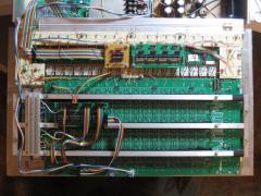
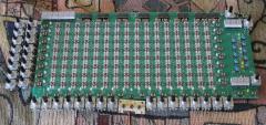
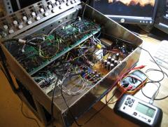
MIDIbox ASIDITY: 3 cores chatting (MBNET operational!)
Sauraen posted a gallery image in MIDIbox Gallery
From the album: MIDIbox ASIDITY
Because the forum software won't let me embed .png images...? -
MIDIbox ASIDITY: 3 cores chatting (MBNET operational!)
Sauraen posted a gallery image in MIDIbox Gallery
From the album: MIDIbox ASIDITY
-
Thanks, that makes more sense, I didn't realize there was a hardware-level acknowledgement signal. Your explanation is nice and clear--I just need a better scope! I'll see what I can do with my cheap one though. :( Edit: Well, that didn't take too long! With three cores connected, the current draw was such that the resistance in the fuse between the 3.3V output of my PSU and the 3.3V rail of the synth made the core voltage drop to 2.8V. Interestingly, it was like this while I was recording the last video last weekend, and the SID core controlled the OPL3 fine at 2.8V, but evidently that wasn't enough for MBNET to work. I upped the size fuse and the cores started getting 3.25V again, and after a little resetting and fiddling (it works with two cores' pull-up resistors but not three, so I cut one off), they started seeing each other! Now for some control of some OPL3 parameters, and finishing the OPL3 driver (so you can start on the application layer for MIDIbox FM 2.0! :P ) Thanks for the help! Bought you a beer. :)
-
"Grungy distortion" is right, it's the most controllable all-passive diode limiter I could come up with. We showed a simple version in our second video, but these are more fine-tunable and (for most settings) clip at lower levels to fit better in the mix. Glad you like it!
-
After a year, finally another ASIDITY video! Those hoping to build a MIDIbox FM with an LPC17 core will not have to wait long for a complete driver!
-
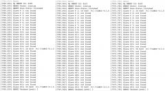
I'm using Ubuntu Linux AMD64, but I also have Windows 7 and access to a laptop with Mac OS X (Leopard?) if that is necessary. I only occasionally get the "(1 ignorable errors during upload)" message, so I think it's pretty stable; though I recently have been getting "Error 14: Bad SysEx message" or something when uploading to one of my cores. Putting it into bootloader mode fixes that. Anyway, to get back to the MBNET: I have three cores with different sections of the board stuffed for each (as per the requirements of my build), and I checked the CAN hardware on all three. It seems to be fine (continuity from LPCXPRESSO module, correct 1k on each board, correct diode voltage drop in correct direction, connected to +5--though should it be connected to +3.3 instead, since that's the core voltage?) I have been trying the MBNET application with different pairs of the three cores. The following all happens whether or not the CAN wire is connected between the cores. If I compile the application with the node ID being initialized to a slave node, in this case 0x05, the core starts up with "[MBNET] initialized------" and when I type "mbnet", says that MBNET is running (and that it can't find any slaves). If there are two cores like this connected with the wire, telling them both to reconnect does not make them see each other. However, ff I change the node ID to a master node, in this case 0x00 or 0x10, or compile the application with this as its node ID: [1992.086] set mbnet_id 0x10 [1992.089] MBNET ID changed to 0x10. [1992.089] [MBNET] sent REQ: ID:0x00 TOS=3 DLC=0 MSG=00 00 00 00 00 00 00 00 [1992.089] [MBNET] ERRORs detected - permanent off state reached! [1992.090] [MBNET] sent REQ: ID:0x01 TOS=3 DLC=0 MSG=00 00 00 00 00 00 00 00 [1992.091] [MBNET] sent REQ: ID:0x02 TOS=3 DLC=0 MSG=00 00 00 00 00 00 00 00 [1992.092] [MBNET] sent REQ: ID:0x03 TOS=3 DLC=0 MSG=00 00 00 00 00 00 00 00 [1992.093] [MBNET] sent REQ: ID:0x04 TOS=3 DLC=0 MSG=00 00 00 00 00 00 00 00 [etc.] Once the core has been put in permanent off, nothing but resetting it turns on the CAN again. Even after changing the node ID back to a slave node and telling it to reconnect, it still says that the bus is permanent off. This is complicated by the fact that once I get it working, I need all three cores to be masters!
-
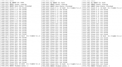
It being the wrong pin would explain me not seeing data on that pin! Now my cheap scope shows a peak-to-peak voltage of 2.0 V when set to 50 ns, even though I still can't see the data. But it's still not working. The app compiles fine and seems to work fine, except neither core sees the other. The only things I changed are a) the MBNet ID of each core, making one 0x00 and one 0x20 and compiling a version for each; and this in mios32_config.h: #define MBNET_SLAVE_NODES_MAX 33 #define MBNET_SLAVE_NODES_BEGIN 0x00 #define MBNET_SLAVE_NODES_END 0x20 Once both were running, I told each to refresh, even changing the MBNet ID of each at runtime. Both continued to refuse to see each other. I managed to reboot one core and refresh MIOS32 in time to catch this on the terminal output--this was while the other core's ID was set to 0x01: [6071.315] reset [6075.392] [MBNET] ----- initialized ----------------------------------------------------- [6075.393] [MBNET] sent REQ: ID:0x01 TOS=3 DLC=0 MSG=00 00 00 00 00 00 00 00 [6075.393] [MBNET] ERRORs detected - permanent off state reached! [6075.394] [MBNET] sent REQ: ID:0x02 TOS=3 DLC=0 MSG=00 00 00 00 00 00 00 00 [6075.395] [MBNET] sent REQ: ID:0x03 TOS=3 DLC=0 MSG=00 00 00 00 00 00 00 00 So it looks like it's seeing something from the other core, but immediately turning off. [see edit] Edit: Also, thanks for your quick work on this! Edit: I managed to get two instances of MIOS32 open without breaking the kernel MIDI pipeline :smile:, and can see the output from both cores. For both, as soon as they send their first REQ, the error message comes back, even though one core is 0x10 and one is 0x00. So it's not that it's seeing the other core but getting a badly formatted response or something--it's failing when it's trying to send the message. Edit: Sorry, last edit! Same problem happens whether or not the actual CAN cable is connected between the cores. :(
-
All right, so I should still have both cores call MBNet_Init(0) and MBNet_NodeIDSet() immediately upon power-up, but then wait a few seconds before calling MBNET_Handler()? If it does go into bus off state, will calling MBNet_Init(0) again turn it back on? The core only responds to incoming messages in MBNET_Handler(), so it won't respond to the other core if it isn't yet calling MBNET_Handler() because it's still waiting the three seconds. But if it has called MBNET_Handler() first, the other core won't respond and it'll turn off. I'm having a little trouble understanding how a core can only turn MBNet fully "on" after receiving acknowledges from another core, but it can only send acknowledges once it's fully "on"!
-
I'm trying to get basic MBNet communication set up between two LPC17 cores. I initialize MBNet with MBNet_Init(0) and then MBNet_NodeIDSet(), and then I have a RTOS task set up to call MBNet_Handler() every ms. On initialization I get the message "[MBNET] ERRORs detected - permanent off state reached!", which I assume means something in init failed, but I can call MBNet_Init() again and get a whole lot of "[MBNET] sent REQ: ID=[etc.]" which all look correct, and which looks like it's actually sending data. According to my cheap pocket oscilloscope there is no data on the CAN pin at all, it's just +5V (whether or not it's connected to the other core, and even while it's sending lots of REQs). Of course, the other core running identical code but with a different master node ID does not react in any way to the messages I'm trying to send (or I wouldn't be asking the question!). Is there some sort of software switch I have to turn on to use MBNet, like MIOS32_MBNET_ENABLE or something like that? Otherwise, what could be going on?
-
Cannot install lib32gmp3-dev for MIOS32 toolchain
Sauraen replied to Sauraen's topic in MIOS programming (C)
I installed every package that contained "libgmp" or "lib32gmp", including both "lib32gmp3" and "lib32gmp-dev" (but with "lib32gmp3-dev" still not working), and now MIOS tutorial applications compile. So I guess it's fixed? Anyway, I can code away now!