

Sauraen
-
Posts
460 -
Joined
-
Last visited
-
Days Won
26
Content Type
Profiles
Forums
Blogs
Gallery
Everything posted by Sauraen
-
Good catch, you are correct. However, as you can see from the "PANIC" statement, the execution should never be there; if it is, something else has already messed up. I was having trouble with some other code and the synth was crashing in the sound-chip-sending routines, so I was trying to isolate the problem. The function is declared void, so there's no value to return at the end.
-
Looks like you got it now. The one thing I still think you should remap with those lookup tables is the operators. For instance, the first set of registers for the operators for the first channel are at 0x030, 0x034, 0x038, and 0x03C; then the next channel, the operators are at 0x031, 0x035, 0x039, and 0x03D. But you will probably want to keep the numbering more consistent in the driver, so that channel 0 has operators 0,1,2,3; channel 1 has operators 4,5,6,7; etc. This means you will need a lookup table to say something like static const u8 OPN2OperRegOffset[12] = { 0x0, 0x4, 0x8, 0xC, 0x1, 0x5, 0x9, 0xD, 0x2, 0x6, 0xA, 0xE }; Also, speaking of the SSG-EG and undocumented features, there's two "Illegal" modes for Channels 3/6. Anyone know what they do?
-
Thanks for the videos, the formant synthesis is cool. I didn't look too closely, but it looks to me like the SSG EG affecting an operator's EG can be done on any operator, since the register for it is duplicated for each operator. I'm not sure what that does for Key On and Key Off; maybe it just affects the envelope for that operator? I guess I wasn't that clear about the typedef thing. When you write typedef union { //blah blah blah } my_new_type_t; you're defining "union { /*blah blah blah*/ }" to be a new type my_new_type_t. It's a little confusing since the name comes at the end, but that's how it is. The "_t" is a convention; you've probably seen things like "size_t" or "time_t" in the C standard. But anyway, then you will see in opl3.c the code "opl3_chip_t opl3_chip[OPL3_COUNT];", this actually makes an array of opl3_chip_t's that's OPL3_COUNT long, that's called opl3_chip. The version of this in opl3.h that starts with "extern" actually is like a function prototype, it's there so when the header is included by other files, they will see that this variable is defined, but "extern" does not actually allocate memory for the array. As far as the nested unions/structs, you can think of every union as holding all the different names for the same data, and the struct as setting out elements one after another. So: typedef union { u8 ALL[3]; //This allows us to access the data byte by byte in an array if we want. struct { //This struct is also a total of three bytes long, and it refers to the same //three bytes as ALL[3], but with individual names. The struct itself is not named; //you can leave out the name if it's in a larger struct or union. //Byte 0 u8 fnum_low; //The bits will be in the right order for the OPL3 //Byte 1 u8 fnum_high:2; //These will be bits 1:0 of the second byte u8 block:3; //These will be bits 4:2 u8 keyon:1; //etc. u8 dummy:2; //Byte 2, and I'm going to provide two different sets of names for that byte. union{ struct { //First set of names gives us synthtype, feedback, and the outputs one at a time. u8 synthtype:1; u8 feedback:3; u8 left:1; u8 right:1; u8 out3:1; u8 out4:1; }; struct { //Second set of names gives us the outputs as one 4-bit integer. Since we already //have the first 4 bits covered, but we have to get past them to get to the second //four, we call the first four dummy2. u8 dummy2:4; u8 dest:4; }; }; }; } opl3_channel_t; You're asking about the bit direction D7:D0. I made sure to get it right here, of course it works, so just do it the same way. The first bit that appears is the lowest bit, D0, and yes the other bitfields are in the right order. Use examples (these are all from opl3.c): opl3_chip[chip].vibratodepth = tmpval; opl3_channels[chan].left = tmpval; //tmpval is a 1-bit value opl3_channels[chan].dest = tmpval; //tmpval is a 4-bit value; note that this is writing to some of the same memory as the last command opl3_operators[op].attack = tmpval; u8 data = opl3_operators[op].ALL[reg]; //an example where ALL is read, this is when getting a byte from memory to send to the OPL3 Also important are the maps (listed under "Lookup Tables"). These took me a while to figure out, so don't be upset if you don't right away! The point of them is that the registers in the sound chip are not in a nice pattern--well, they're in a pattern, but it's not nice. As described in that long comment in opl3.h, my driver does the conversion between a sensible scheme listed there, and the OPL3's internal numbering; these lookup tables are what do that. You will need a similar system for the OPN2, though the actual mappings will of course be different. Also, get used to 0-indexing! u8 blah[4] has elements 0,1,2, and 3, which are the first, second, third, and fourth. :) "blah[4] = something;" will crash. So the second OPL3 is chip==1.
-
Okay, so it's triggered from Timer A, I didn't realize that. Do you have any samples of someone using this EG to produce some sound? At the very least it seems it could be used for some sort of ring mod effect. Just a reminder that I want both the distorted Mega Drive filter and the clean Mega Amp filter. Please, go ahead and ask. I can't directly help with development right now, but I want to build two of these this summer, so I want to make sure everything is as good as it can be. For starters, typedef some_type your_new_name simply makes a new type that's some_type that's called your_new_name. For instance, somewhere in MIOS32 is typedef unsigned int u32; typedef int s32; typedef unsigned short u16; etc. A union is like a struct, but the elements all share the same memory--they're on top of each other, not one after another. For instance, compare:, union{ u32 a; u8 b[4]; } //versus struct{ u32 a; u8 b[4]; } The first is 4 bytes long, the second is 8 bytes long. And in the first, you can access that same data either all at once with a, or one byte at a time with b. Here's another example: union{ u8 all; struct{ u8 bitfield1:3; u8 bitfield2:1; u8 bitfield3:4; } } This is one byte long, and I can access that whole byte, or the bitfields within it. One step past this is what I have in opl3.h.
-
Ahh, that explains why I was getting them confused. I didn't look at it too closely, but where's the actual control registers for the SSG EG? The registers mentioned there are the registers setting how much each voice is affected by the EG, not setting the period and mode of the EG itself. Anyway, how's the project coming? Not only do I plan to build one for myself this summer, but I know an indie game composer (who shall remain nameless for now) who wants me to build him one as well. So I will need eight sound chip boards! Bulk order time! You've already done the layout for one, right?
-
We should have plenty of room for both, especially considering the low quality. But of course people will want to edit samples on an SD card, even if that's a pain. :smile: The OPL3 has four-channel output: L, R, and outputs 3 and 4 which are usually unnamed. These are the bits for whether that voice is sent to each destination; I'm pretty sure bit 0 is L, etc. On OPN2 this would be two bits, and the field would be absent on PSG. Sorry that was confusing. When I write u8 dummyA:B, B is the bit width of the unused bits, which has to be correct; and A can be anything, as long as two fields don't have the same name. I just incremented A every time I needed another dummy. So you can have u8 something_useful:3; u8 oasfbklasdfkabdf:3; //this is dummy u8 another_useful:1; u8 aoskdbflsdfbbs:1; //this is dummy but not u8 something_useful:3; u8 dummy:3; u8 another_useful:1; u8 dummy:1; //error, multiple declaration of "dummy" Yes, you can put whitespace wherever you want in C, as long as it's not in the middle of a word. (Or in a preprocessor command like #define, those care about whitespace.) So you could have static const u32 OPL3CSPins [ OPL3_COUNT ] = OPL3_CS_PINS ; Try it! (Well, not like that! Most of the time extra spaces are inserted to make things line up nicely.) Pardon the n00b question, but what does SSG mean? I didn't know there was a difference. I meant to be referring to the TI chip.
-
-
In my MIDIbox FM V2.1 (with STM32F4), I used this adapter cable: http://www.ebay.com/itm/50cm-USB-2-0-B-Female-socket-Printer-Panel-Mount-to-USB-Micro-B-5-pin-male-cable-/291006031451?pt=LH_DefaultDomain_0&hash=item43c14fa65b Much less risky than desoldering SMT, and it has worked fine so far. Of course, this assumes you're only using the STM32F4 as the USB Device, i.e. plugging it into a PC.
-
How about something like this? 1U but a 2x40 LCD and enough buttons that all the parameters could be available in menus. I'm thinking for the buttons on the top row, hold it down and select one of the 8 softkeys (corresponding to 8 choices on the screen, but there's no room to fit the buttons under the screen).
-

From the album: MIDIbox Quad Genesis
See Yogi's proposed project in -
-
Actually from looking at the datasheet it looks decently similar. The parallel interface should be nearly identical. Just change the register definitions in the header file, and then change the OPL3_SetWhatever() functions to match. If you wouldn't mind, when you write all the code, please make the number of sound chips a preprocessor variable (like I have OPL3_COUNT). It might be more complicated because you want to have multiple different chips running on the same parallel interface. I am still a little confused about all the OPN series chips, which include the SSG and which don't, and which type of SSG to use externally. The most flexibility is of course the best, especially at the driver level. But I understand completely if you want to just make the driver support a YM2612+SN76489 or YM3834. But it would be nice to support large numbers of each. I see on eBay 10x SN76489 for $6 total--that would be a cool sound! 10x YM2612 is a little more expensive at roughly $30, but imagine the polyphony! Oh well. I would settle for a single Genesis, but two would be nice. I understand that at the application level, there are separate MIDI channels for each sound chip channel, and you might not have enough to implement two or four separate groups; but you could map them to separate UART MIDI input ports, or separate virtual USB ports. I just got a few cheap 1U rackmount cases; and from my previous projects, the front panel is the most time-consuming part of the project; so if I did build one of these this summer, it would probably be a rackmount with four Genesises (4x YM2612 and 4x SN76489), with a minimal control surface, but four MIDI IN ports and one USB MIDI port that had four virtual inputs, each mapped to one Genesis with that scheme you mentioned above. I think the STM32F4 is powerful enough (in this case, I mean quick enough, it certainly has enough RAM) to run four Genesises in parallel; after all, six voices on YM2612 and three on SN76489 is nine voices, times four sound chips is 36; and right now I have the STM32F4 running two OPL3s, which is also a total of 36 voices. The LPC17 would lag a bit when I was using 30-33 of them at once; the STM32F4 does not, at least not noticeably. Edit: Also you might want to start a new topic for this. :)
-
The code is up! It was much more painless than I had expected, and nearly the same procedure as git. Oh well. I am happy to now be a published programmer! I would recommend you start with making the sound chip driver, starting by copying and pasting the OPL3 driver. Of course the data structures and functions will need to be changed, but some of the code will not. Then I would suggest making a simple mios32 app that plays notes on one of the channels, and from there test the driver.
-
I was going to suggest a switch to toggle between Genesis 1 and 2 filters, the former with the original distortion. Can't quite tell if that Mega Amp lets you switch between filters.
-
I should be able to put up the code this weekend. Just to mention, SD card bandwidth is not great either, though the files you're talking about may be small enough to load entirely into the huge 192kB RAM of the STM32F4 (of which less than half is used for MBFM, including MBNG and MIOS32). It should be easy enough to hard map the sound chip voices to MIDI channels, and keep the framework I have in place for modulation, patch loading/saving, etc. Changing what the modulated parameters are should be straightforward, though of course it will take some work. Much of the complexity of MBFM2 is keeping track of multiple voices as one channel, with polyphony and two kinds of linked parameters. I have also always wanted a Genesis synth. I don't have time this semester to build or code anything else, but if you have a PCB made with a group order, this summer I might like to build one. I can help you debug the code, but I probably won't have time to do any development myself.
-
I apologize for not having put up the code, I've been very busy this semester. TK did give me commit priveleges so it's just a matter of spending a few hours putting in the right preprocessor commands to make the driver specified for STM32F4 and all that, and trying to commit it without ruining the repository. For your design, are you planning to use it primarily for real-time performance, or controlled by a DAW like a tracker? If the former, my synth engine might be appropriate; if the latter, you probably want to write a simpler application that puts each of the voices permanently on a different channel, and controls all the parameters from CCs. On my synth, I've considered MIDI file playback, but right now I can do that just fine by playing a MIDI from my computer into the synth. Probably the best way to support Adlib or something like that, would be to write a Juce program that reads the file format and outputs custom MIDI messages to the synth for notes and all the controllers. On the other hand, I do have to admit that I never wrote the part of MBFM V2.1 that lets you control all the parameters of the voices from CCs; only standard CCs like volume, pan, mod wheel, and sustain pedal are implemented, not things to change the actual parameters of the voice. This is partly because the synth supports making sounds that use several voices--you could, if you had the patience, set up all 36 voices as a single monophonic sound, maybe with detuned saw waves or something!--and I never figured out how to let you use CCs to tweak individual parameters within those voices, since there would be several hundred in that example.
-
Demo video of the Electone, still no real mods:
-
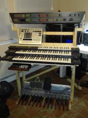
It works! This is just the organ as it was before I took it apart and shipped it, minus the amp, speakers, and amp PSU. Also, most of the motorfaders no longer work, though some do; I thought they all worked before I shipped it, but maybe not. Based on the front panel design (from the schematic), it doesn't seem likely that any mistake I made would have messed up the motorfaders, so maybe it's just age and old belts.
-
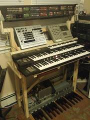
From the album: Sauraen's Modded Yamaha Electone FX-20
It works! This is just the organ with no mods yet--well, other than removing the amp, speakers, and amp PSU, not to mention building a custom stand... -
Mechanical assembly mostly complete (as you can see from the photo above), I've been plugging in the wiring harness... Hopefully I will get some sound out of it soon! There are no significant electrical modifications so far, other than leaving out the amplifier and its PSU and all the speakers. A friend suggested I install LED strips on the organ... I have some spare I/Os that I can hook to PWM channels, he he!
-
From the album: Sauraen's Modded Yamaha Electone FX-20
See -
So I have a friend who's a pastor in a house church. A couple years ago, I suggested to him that he look on Craigslist for an organ for his church (living room), since he was just using a cheap keyboard, and often people will list organs for cheap (or free) if you can get the monster out of their house. He's a professional home improvement contractor, so that kind of moving is not difficult for him. After several adventures, we found a guy who was willing to donate his near-mint Yamaha Electone FX-20 to the church, and we moved it in. I had a lot of fun with it! Now the pastor's family is moving to Ireland, and getting rid of their house... and they need to get rid of the organ. However, I can neither fit an organ in my house (I'm an engineering grad student living with other students), nor can I get the organ from his house to mine (~800 km away). However, he has a friend who wants to turn the organ cabinet into a writing desk... so I get all the guts! I'm on my way to visit the city he lives in, and I have a couple days to carefully dismantle the organ and ship all the parts back home. I already built a wooden keyboard stand with (the photos there are not up to date), and I will modify it to hold the manuals and the organ's electronics. For now, I will hook an external audio output to my mixer and monitors, instead of using the original (quite nice) integrated speakers. The Electone FX-20 has 2.5 manuals (all with velocity and aftertouch) and pedals, a large control panel (including motorfaders on all sliders, and drawbars for the Hammond-like section), a basically-uncountable number of operators of FM synthesis (around 50 voices and 200+ operators), and an auto rhythm/accompaniment section, all made with the best 1983 technology. However, it doesn't have MIDI output, pitch bend, mod wheel, octave buttons for the main manuals, etc. So a custom controller is necessary! I have gotten the information I needed from http://tsstech.org/electronics/fxmidi.html (especially http://tsstech.org/electronics/fxtechinfo.html ), and from the service manual for the FX-20 which I was able to order from Yamaha for $16. Based on the project here, I've designed a board which "sniffs" the manual and panel interfaces from the organ's own controller, and spits out MIDI messages corresponding. I decided not to use mios32, because all of the timing has to be synchronized to the organ, the panel SPI has to operate in slave mode, and I need very many I/O pins to scan the matrix interface to the manuals (a shift register scheme would likely not be fast enough). I settled on an Atmel ATxmega128A1 on the mikroXMEGA development board, for the number of I/O pins, the relatively low price, no SMT soldering, and the fact that I've used the Atmel ATmega series (similar) in school. Programming will be with Atmel Studio via JTAG with a AVR JTAGICE MK II that I was able to obtain. I decided on assembler for fast speed and ease of configuring multiple hardware/software interrupts--no FreeRTOS here! Features: Follows the FX-20's controller scanning the manuals and pedals. Reads break and make contacts, measures velocity. This involves 13 hardware interrupts for the matrix rows, and then reading about 30 column lines in after each row selection. Uses SPI to scan my custom pedalboard (pictured above), actually using a MBHP_DIO module. In same scan cycle, also scans custom pedal chord buttons I designed (not pictured, proprietary information! ;) ) Pretends to be the FX-20's pedalboard to the FX-20; outputs the corresponding pedal signals on the pedal interface to the FX-20 based on what it has read from my pedalboard. Follows the FX-20's near-SPI panel interface. Sniffs both DIN (button, slider states) and DOUT (LED, motorfader commands) on a single slave SPI channel with a digital multiplexer selecting which signals are being read. Same SPI interface also scans drawbars (non-motorized faders for the organ section, which are on a separate hardware serial chain). All the sliders in the organ (motorized or not) are actually 8- or 16-position switches masquerading as slide pots, so there's no ADCs or noise issues. Sniffs the analog inputs in the organ: expression pedal and the three manuals' aftertouch signals. Five MIDI output channels (this chip has up to 8 UARTs!): one buffered and connected to 4 MIDI ports, the other four connected to one port each. The individual ones are the outputs from the three manuals and pedals individually, and the four together are outputs from the whole organ (the manuals on different channels). Sustain pedal switch input. Custom controls PCB: for each manual and pedals, whether sustain pedal and expression pedal apply to them; an extra slider to control a configurable CC; a button to set up what channels things are on; and buttons to set up what CC each slider on the front panel corresponds to, and what program change each button on the front panel corresponds to. Includes 2.5 digit LED display, and designed to look like the organ's interface. A custom-designed pair of controls for pitch and mod wheel for each manual. No pictures, proprietary design! (I would have just put up the design, but an engineer friend of mine says it might be patentable...)
-
Of course not! I'd be happy to help. That is correct. According to the OPL3 datasheet (and this has worked for me), all the pins can be driven with 3.3V except the reset pin, which has to be at +5V when you don't want the chip to be in reset. The reset pin is called /IC ("initial clear") on the datasheet, but to me "IC" stands for "integrated circuit", so that's why I said "RS" for "reset"; the /RD pin is a read strobe, which should be connected directly to +5V (it is on the OPL3 board). I put the 8 data lines on J10 because there were already-existing subroutines to write the 8 bits at once; the other pins can be freely moved around (changing the configuration in the source code appropriately). The reason I put the /IC signal on J19:RC1 or RC2 is because those are buffered to +5V; you can move this signal to another pin, but then you have to make a simple level shifting circuit to interface it to the /IC pin of the OPL3. I never actually drew schematics for this... ;) I have a module driver for the OPL3 chip for LPC17 and STM32F4 that will do the low-level communication, and give you functions to set each of the parameters of each of the voices/channels. I could email it to you, but maybe there is a better way. TK, if you're reading this, where should I put up this code? On the wiki? Would you be able to give me commit privileges just for the folder mios32/trunk/modules/opl3/ ?
-
I've been working on some software to import/edit/export MIDIs from the internal sequence format (Audioseq) used in first-party N64 games. I finally got MIDI export working (though the instruments are all wrong, they're stored separately)... so what better to play the MIDIs through, with editing instruments and drum mappings, than MIDIbox FM V2.1 with GM sound bank?
-
New demo video! MIDIbox FM V2.1 playing Zelda Majora's Mask: End Credits (Part 1) by Koji Kondo, a MIDI exported from the ROM using some software I'm developing.
