

mackeSID
-
Posts
17 -
Joined
-
Last visited
Content Type
Profiles
Forums
Blogs
Gallery
Posts posted by mackeSID
-
-
Hello!
I've seen the amazing stuff that can be done with later revisions of the chip (6582 & 8580), with feeding the output signal back into the input causing the filter to act like a 4-pole configuration.
I've done some research on this and I've found the 6581 I have doesn't seem to work the same way.
After activating the filter in function of my sammichSID, I've used an analog DJ mixer to mess around with the signal before feeding it back to the input by using the headphone output plugged into the input on the Sammich.
What I've found is that the input can be saturated which creates huge amounts of bass, as well as a nice n round clipping effect, but no crazy resonant stuff like the ones provided at this page:
http://www.bigmech.com/misc/c64mods/feedbackloop.html
According to the 6581 datasheet, the input is supposed to be around 300mV, so I've tried staying just below that when feeding back the signal.
Also, the only reference to the filter is that it uses integrating capacitors.
Am I correct in assuming this means it's an OP based filter with a software-adjustable resistive component to control the cutoff frequency?
I'd really like to understand how one could increase the filter order, as I use my sammich alot for TB303-ish basslines. ^_^
Have it good
/M -
Another hardware jam, this time completely unedited.
Some small glitches with getting the Sammich to start playing tight with other gear.. Usually I quickly flip between playback speeds but when it doesn't work I have to stop/start again.
Anyone got any tips on how u handle this?Rilly love my Sammich more and more for every day. ^_^
-
Yeah, i've seen it. I don't understand why he's chosen to wire pin 2 & 3 together like that.
I've used a 200k pot, doesn't seem like the value of the pot should matter very much since it's just voltage division.
What is it that you don't understand? -
Hello!
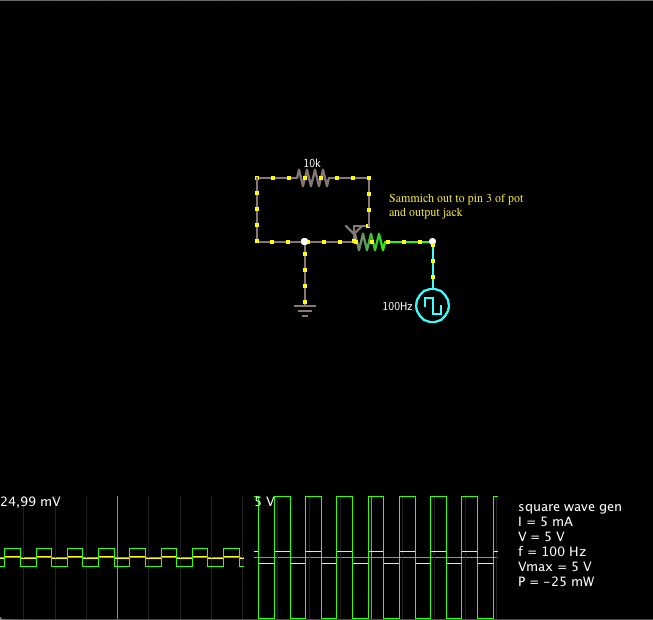
I attempted to make a feedback loop plug for my Sammich, where the output is split between a female jack and a male TRS connector.
The image corresponds to the wiring, where the square oscillator (output of Sammich) is wired in parallel to the female output connector and pin 3 of a potentiometer.
Pin 1 of the pot is set to ground and the washer pin is wired to the male TRS connector that goes to the Input of the Sammich.
The wiring shows a mono connection but I've made it with a stereo pot so leftOut->leftIn and rightOut->rightIn and the 10k resistor just symbolises the input of the Sammich (no 10k on actual wiring, only for simulation purposes).However, I cannot hear any difference with the pot turned each way, not even when activating the filter in on the patch loaded.
What am I doing wrong?
Cheers
/Macke
-
That's right Shuriken, I had some problems in the 200-Hz area and made a remix ;)
-
Has anyone successfully done the feedback mod?
Is it any different depending on the model of the SIDs?
-
Thx peeps!
I'm leaving Ableton for a while now, much more fun playing out of the box! ^_^' -
Seems like the only thing transmitted through the MIDI Out is MIDI clock.
A pity, since the step sequencer is badass, I'd love to let it control another of my synths, is this possible?
Cheers
-
Here's my first live jam with my Sammich, I started experimenting with the step sequencer and found it to be most enthralling!
-
Not quite sure what to do with those files, opening them in VectorDraw produces mostly empty documents..
I found this, but I don't understand the unit of the measurements provided (4000*6000 enclosure.. What, millimeters? :)
-
Hello!
I'd like to lazer cut my own panels of this beautiful little synth, can anyone provide me with drawings with measurements, please?Regards
/Macke
-
Hello!
I have now reached the level of finishedness that I should get to installing the SID-s.The flashing of the EEPROM was successful after some turns and troubleshooting that turned out to be caused by me not soldering one of the MIDI out legs.
Silly mistake.
The previous strange values was the multimeter being low on battery..
Now I get a steady 11.29 V between pin 28 & 14 on both SID-sockets.
All values seem slightly lower than they are supposed to be.
I've tested two PSUs of the same kind and two different multimeters (now with sufficient battery power) so I'm still hesitant to installing the SIDs.
The value seems very low indeed but is it a safe low?
The uploading of the application went fine as I said and now I get the beautiful startup sequence when I power on the device. ^^
Regards
/M
-
Hello!
This is my first post, rilly excited!
I'm approaching finishedness of my sweet Sammich and I'm having some questions popping up.
First, not such a big deal, is the LCD display.
There are some details about how to put the jumpers depending om what kind of lighting the display has ( edge lit vs LED array).
However, I can't for the life of me make out any indication as to what kind mine is!
The only hint as to what it might be is on the front, where there's a small "5V" in between the display and the encoder.
Oh well, I set the jumper config to the 25mA settings to play safe and I seem to get the screen to start up after doing voltage tests and plugging it in.
Now to my main problem..
Seeing as the manual strictly states to Never use 6581's (R4, which mine are) with the JP set to 6581 (which I have) with an unregulated PSU..
Well, I thought I got a regulated one from the store.
It's an adjustable one, and measuring it up produces some strange results.
It's supposed to be 1000mA regulated PSU.
Measuring the current gives me results sligthly below 3(!) Amps.
Also, the output voltage (unloaded) set to 12V gives me around 14.5 V.
Plugged into the unit (without the SID-s installed) gives me slightly lower results.
The 9V setting produces about 11.9V unloaded.
I'm unsure of the brand, but I got it from here:
http://www.electrokit.com/batterieliminator-1-512v-1000ma-stab.49112
Thanks for a great community and a beautiful product!
Regards
/M
-
Just got myself a package of crisp 6581 R4s from AndroSID and wanted to say that he's is a great guy to shop from!
Have it good
/M
Hard techno jam
in Songs & Sounds
Posted
Thanks!
Mostly achieved by driving the input of my Monotron Delay, such a versatile little device! ^_^