Highcooley
-
Posts
95 -
Joined
-
Last visited
-
Days Won
3
Content Type
Profiles
Forums
Blogs
Gallery
Everything posted by Highcooley
-
I do cool my 6581s with heatsinks. So I just unplug the fan and see what happens on the long run :-) Thanks for the hint! Cheers Andy
-
Connecting a 5V fan (ADDA, AD0405DB-G70, brushless) to J3 causes some audible noise on the 5V rail (I am not talking about the mechanical air flow noise). It is a 10mV pp ripple somewhere in the mid audio band around 0.5-2.5kHz. Did anybody have the same issue and does know an easy solution for that? I tried several condensators in parallel to the fan, but so far it didn't help (no change at all). Interestingly, I can barely hear it over the PA, but it's very annoying over the pre headphones directly at my mixer.
-
Thanks for your reply! That would be awesome if you could actually make this happen! Hmm, either new AOUT targets or the availabilty to combine several values e.g. AOUT1 = NRPN2 + NRPN1 Cheers Andy
-
Hey everybody! I'm learning more about the Midibox_NG every day. So far, I am able to read out analog and digital signals, assign them to CCs or NRPNs and routing them to outputs. It is truly amazing what you guys accomplished with this Midi platform. Kudos to you! What I am looking for at the moment is a way to add, subtract or scale (divide) two or multiple NRPNs, CCs or even a combination of both. My application is to fine tune a Midi note value by an AIN pot (+- 2 semitones) before sending it to an AOUT. As I build a three VCO analog synth, I would further like to scale the frequency for each oscillator by an octave rotary switch (6 octaves) as well as a detune AIN pot (+- 7 semitones). One solution would be to waste AOUTs for each setting and combining the voltages in the hardware. However, this is certainly not what I am after, as AOUTs are expensive and I will eventually run out of spare ones, once my full fledged analog synth reaches completion. Does anybody know if this is even possible with the Midibox_NG scripting language and how it can be done? I see three ways how the AOUT part could be done: - Use one AOUT for the fine tuned frequency voltage for all three OSCs together and one scale/detune AOUT for each individual oscillator (4 AOUTs) -> pro: it's the easiest solution, the VCO can be modulated via just the first AOUT. con: four AOUTS needed - Use one AOUT for each OSC and calculate the frequency value out of Midi tone, fine tune, octave and detune value for each OSC individually (3 AOUTs) -> pro: only three AOUTs needed, the solution is still pretty logic and straight forward. con: the modulation of the whole VCO would be much more complicated - Or use a combination of both by using Midinote, finetune plus octave value of the first OSC for all three oscillators (the first OSC doesn't need a detune function for obvious reasons) and then use two other AOUTs to subtract the octave value of the first OSC and add the individual octave settings and detune values for the two other oscillators (3 AOUTs) -> pro: only three AOUTs needed, the VCO could still be modulated as a whole. con: quite a complicated solution. It would be cool, if somebody could point me into the right direction. Thanks for your replies! By the way: Although http://www.midibox.o...i_specification explains the splitting of 14bit values into MSB and LSB, I wasn't able to fully comprehend, how this can be done using the Midibox_NG scripting language. Is this even possible without altering the code of Midibox_NG itself? However, this is not my main question, as the whole Midi_Out part will come later in my build.
-
Wow, thanks, that was a fast reply! And well...it was cable length. They were 18cm from CORE to AINSER and 13cm from AINSER to AOUT. Now with only 12cm from CORE to AINSER, it works like a charm. That was spot on :smile: Have a nice Sunday!
-
Hey everybody After hours of reading, searching and trying, I am seeking your advice. I would like to use an AINSER64 as well as an AOUT_NG Module with my LPC17 Core. As I understand, both modules connect to J19 (for AOUT_NG, this was not clear in the beginning, but the LPC17 core schematics suggest so) and have to use a different chip select for each board in order to differentiate them. The most logic solution would be to connect the AOUT_NG board to J3 of the AINSER64 board, useing RC2 for the AOUT and configure it's cs to 1. Now, one thing I figured out is, that the actual AINSER64 PCB (V1) swaps RC1 and RC2 at J3, which is different to the schematics which can be found online. However, that would not be a big thing and is easily solvable with the right cable. But in the end, I am not able to use the AOUT_NG board with MIDIbox NG, where as the AINSER64 works. If I connect the AOUT_NG direct to J19, it works like a charm. Is there a special trick in the configuration I have to do or do I need to use another port of the CORE? As far as I understand, the ids of both events don't interfer with each other and each of both event types has to start with id 1. Any help is much appreciated! Cheers Andy
-
Ok, problem is solved. Obviously, a lot of configurations in the default.ngc are redundant and are mixing each other up, if the hardware is not specifically designed. Why rubby's code had the same effect, I don't know. However, as long as I set up only the amount of buttons currently in use, it works. Another thing is how to set up the rotary switch to act as it should (same CC but different range/value). But since nobody cared to answer here, I'll post this question in a more apropriate topic.
-
Hi rubby or anybody else using DIN matrices with the DIO_Matrix module Does the above script fully work for you now? I am playing around with a DIN_Matrix as well with the DIO_Matrix module, connected directly to J8/9 without any other modules at that port. However, I do have some issues with everything connected to O7 of J3 at the moment. Whenever I switch on any switch on that output, nothing happens. If i switch it off, it bounces on/off for the same times as the amount of buttons I assigned to the matrix (e.g. 64 times if I have 64 buttons assigned). It is definitely no switch bounce as usual, as I don't have this problem at any other pin. First, I assumed a hardware problem. However, if I interchange the chips, it is still just O7 on J3 (O7 on J4 is ok). I can disconnect my Switch matrix (it's actually three 6 step rotary switches at I0-5 and O5-7 with a single diode at the common pin) and short the pins manually on the DIO_Matrix board and do have the same effect. also the PCB traces are fine and there is no shortcut at any pin. I believe, it has something to do with the configuration. But either I didn't fully get the way this matrix has to be configured (I tried your script as well as an own one with Midibox_NG V1.026) or something strange is going on :-) Everything else I got fully working so far (AINSER64, SD Card, GLCD). Thanks for your help!
-
 Does anybody know what happened to Julian? He suddenly didn't respond to PMs anymore. His last sign in was over a month ago. In my case it was right after he told me that my panel was finished and ready for shipment. We where about to decide for the shipping method when he didn't respond to my answer. Does anybody have any information? All good, we're back in contact after the abrupt Christmas hols.
 -
Communication between multiple PIC cores
Highcooley replied to avockley's topic in MIOS programming (C)
Correct, I2C is a 10bit bus. All in all you could theoretically control up to 1136 nodes over one single bus. However, I would recommend controlling as few nodes over one bus as possible, as I2C is not very robust. 15 nodes shouldn't be a problem at all. Alternatively there is SPI, which is a bit more complex. Check out the different midibox IO modules to learn more about how these buses work. -
Communication between multiple PIC cores
Highcooley replied to avockley's topic in MIOS programming (C)
An interesting project you are working on. I myself am developing a Moog style synth as well at the moment and am thinking about similar questions. Cool to meet another person interested in analog synth development driven by a midibox core. It would be cool to exchange some design thoughts (i.e. about the continuous wave shaper). As I am still in an early stage in the development process (currently tinkering with different VCO and VCF design variants), I haven't actually looked much into MIOS so far. However, I came to the conclusion that using a single LPC1769 for both, user interface and synth would be best for me. As I estimated and also have been told, the module should easily have enough power to read all the inputs, write displays and other outputs, do some math, communicate over midi and drive the different synth modules. As long as you don't do any real time audio or CV signal processing by the core, there is anyway not much going on over the IOs most of the time. My design won't be the most compact one, as I will do all the IOs with standard midibox modules, but it will be modular, which helps to try out different designs and interchange modules but keeping the digital part. Internally, the synth will work with a higher number of bits. When controlled over midi, I cut away the LSB. I know, all this doesn't help to solve your specific problem, but maybe it might be of interest anyway. What I do know however is, that past midibox projects like the MB_SID use MBNET for coupling multiple PICs: http://www.midibox.org/dokuwiki/doku.php?id=mios_pic18f4685&s[]=mbnet What was your reason to go for multiple PICs instead of a single LPC1769 anyway? -
...my words. I'm still tinkering with these Bourns illuminated encoders. As I mentioned, they don't have the same height (the body is 1mm shorter than Alpha standards encoders). And if the detents are being removed, the shaft turns too easily (no resistance at all) and starts to rock slightly. I tried to add some resistance by adding a silicone layer on top of the detents, but so far it doesn't work. Any Ideas are highly welcome.
-
One thing I have to mention is, that the housings of the illuminated encoders are a bit too thin in comparison to standard encoders. So I might need to rise them from the PCB to reach long enough through the panel hole.
-
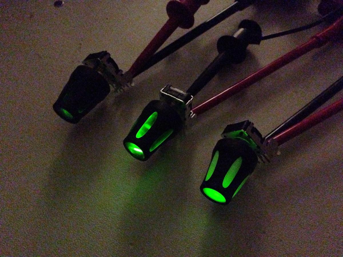
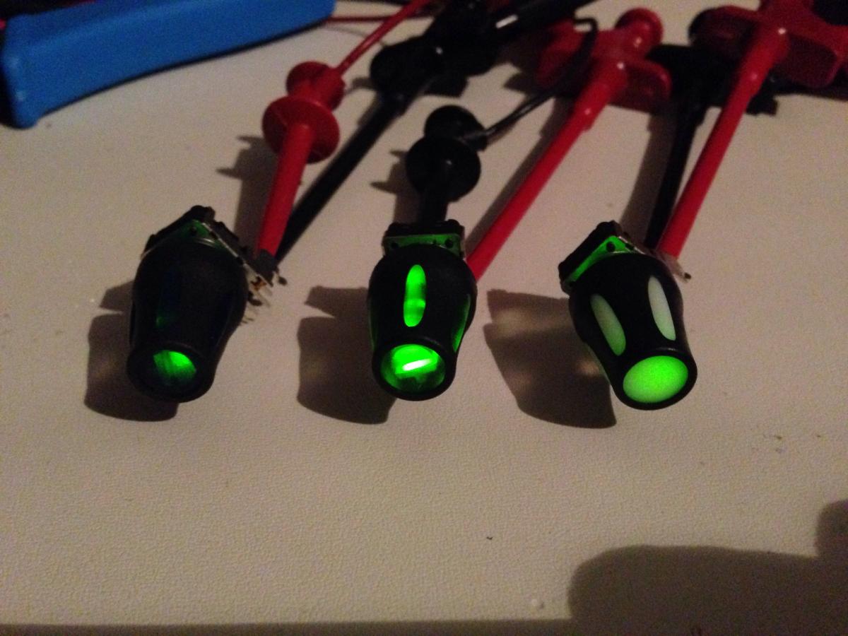
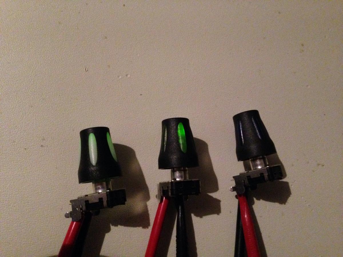
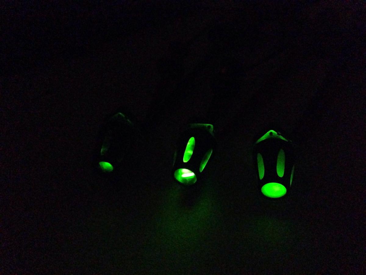
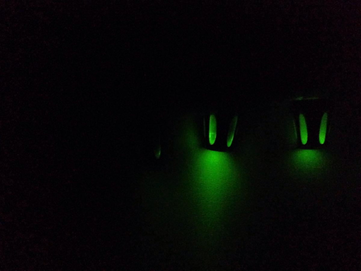
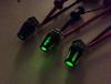
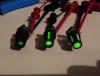
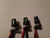
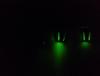
Here we go with a short test of ALBS Waldorf knobs on illuminated Bourns encoders. I found it quite hard to take pictures which show how the knobs look in reality, as the illumination seems to get enhanced on the dark and reduced on the bright pictures. Anyways, here we go with three knob samples transparent blue, clear and milky from left to right/ top to bottom in different lighting conditions. I use the green illuminated Bourns encoders at 1.9V with 14mA. The current could be enhanced to max. 20mA, but suits for the comparison. As you can see, blue doesn't work very well with the green LED, so it's more about clear vs. The new milky option. The clear knob obbiously shines a bit brighter and produces a brighter reflection on the white surface the knobs are on. From the side, it has the interesting inside view with a kind of lens effect, as people who use them know it from theyr own illumination work. The milky knob however has much more even light filling on both sides, the top and the side. Unfortunately, the brightness noticeably decreases down the side from top to bottom. As mentioned, the green illumination on the photos looks a bit brighter in dark lighting conditions and a bit dimmer in bright lighting conditions compared to real life. My subjective impression is, that both, milky and clear knob look fantastic in no light and dim light conditions. With bright surrounding light, the milky still looks fantastic from the top but looses the effect a bit on the side. I am looking forward to receive some SMD LEDs and do another comparison. ...followup: The three LEDs where killed seconds after this post has been published by trying to max out the current with a potentiometer...leads shorted, bang. Now I have only 13 left for my MB6582, grrrr :-(

-
Got my parcel yesterday! Great milky knobs and nice packaging work (although the eatable packaging chips don't taste that good :-)). Thanks a lot for your effort! The illuminated encoder test can be found
-
Yay! Perfect timing for my MB6582 build...
-
@Hawkeye: The thread about the Bourns non-illuminated knobs was the reason for my request... The non-illuminated ones I would use instead, would be the ones from SmashTV. I beliefe, these are Bourns ones as well (don't have one at hand). Anyways, compared to the LED version, they already look and feel a lot more sturdy. @kristal: Of course, I will take some pics of the milky knob and can do a comparison to the clear version, if you include me a sample.
-
Does anybody have some longterm experience with the Bourns LED encoders concerning quality? I ordered a bunch of green ones for my MB6582 from Mouser. Unfortunately, they only have the green ones for horizontal mount. So I have to improvise a bit with the orientation and some mounting brackets. Somehow, the encoders don't look very sturdy. So, before I go into modification, it would be nice to know, if they are reliably and don't break off or skip steps after a short time. Anybody? I'm also not sure, if the LEDs are bright enough to use with the new milky ALBS Waldorf knobs. But that mystery will be solved, as soon as I get some knobs.
-
@kristal: Thank you for your reply and for the effort of asking about the difference in soft and hard material. Hmm, strange that they call it soft even as it is neither rubbery nor satin finished plastic. I'm looking forward to get your update. Cheers, Andy
-
Hey On the wiki page I read "please notice that the max. order amount for the milky knobs (150pcs.) is reached". Does that mean, that you won't be able to get more than the 150 knobs of each type from ALPS, which in the case of the milky ones three people on the list already ordered? Thanks for clearification!
-
Just got a couple of chips from AndroSID. Everything packed nicely and arrived in perfect condition. Thank you very much! I am looking forward to post about my build, as soon as I got the other parts.