

irrobert
-
Posts
17 -
Joined
-
Last visited
Content Type
Profiles
Forums
Blogs
Gallery
Posts posted by irrobert
-
-
I guess you are right. I am going to try. It was one step forward two steps back: I troubleshooted the bootloader (which was not necessary) and it took me a lot of time to get it working properly again.
i am going to try your suggestions: it looks good.
-
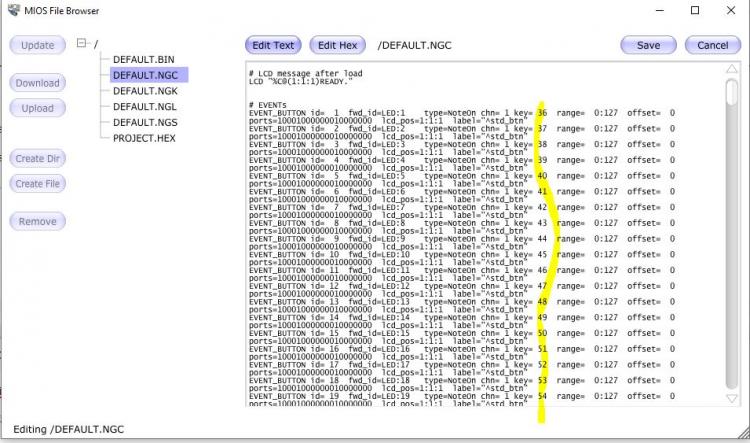
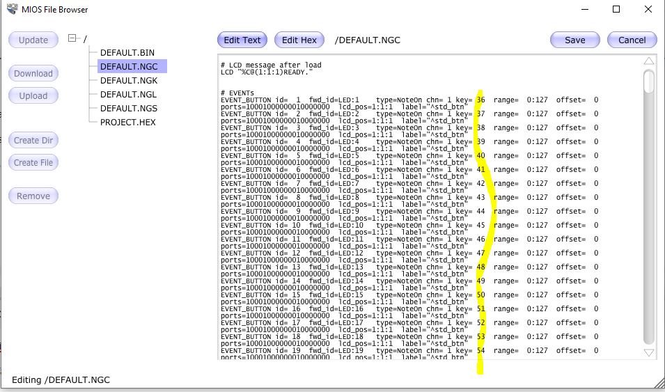
new idea: I switched on the following in default.ngc:
DIN_MATRIX n= 1 rows=8 inverted_sel=0 inverted_row=0 mirrored_row=0 \
sr_dout_sel1= 1 sr_dout_sel2= 0 sr_din1= 1 sr_din2= 0
DIN_MATRIX n= 2 rows=8 inverted_sel=0 inverted_row=0 mirrored_row=0 \result: no output at all when I press the buttons.
-
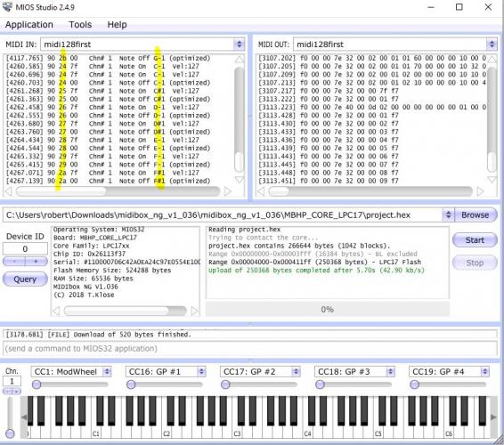
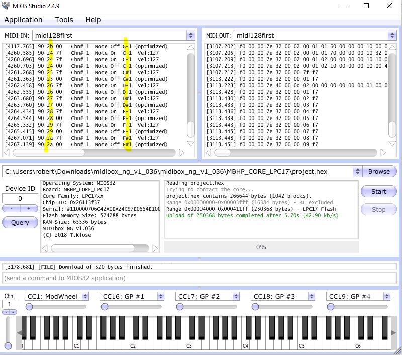
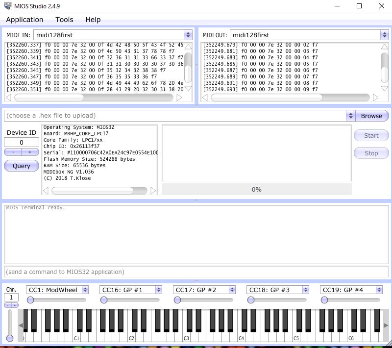
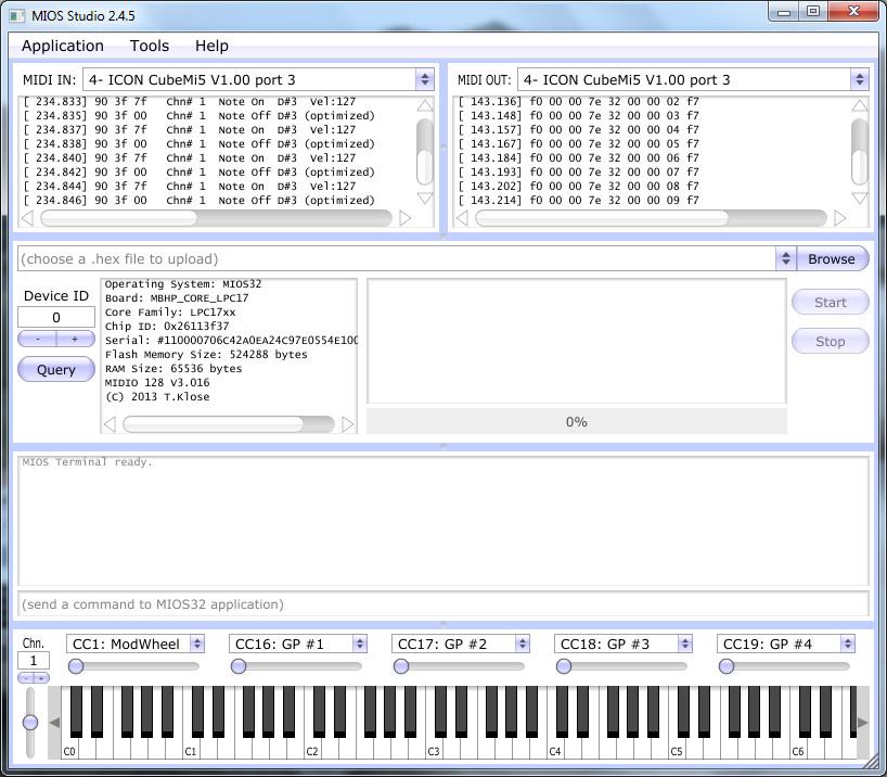
I dowloaded the project.hex (midibox_ng) and it was installed correctly. It created new default.bin and default.ngc on my sdcard.
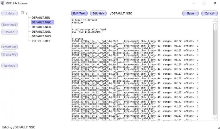
I read the documentation and I studied the default.ngc.
If I press a (knob) button I would expect the folowing results: keynotes between C2 (36) and D#7 (100). This is not the case. All outputs result in keynotes C1 ... G1 (24..2b) (only 8 notes).
Why o why?
-
thanks for the reference.
But I do not see an example for the diomatrix. Only Din4_matrix. Apart from that: I do not think I have to compile a completely new program: only adjust the default.ngc. But how?
Robert
-
Hello,
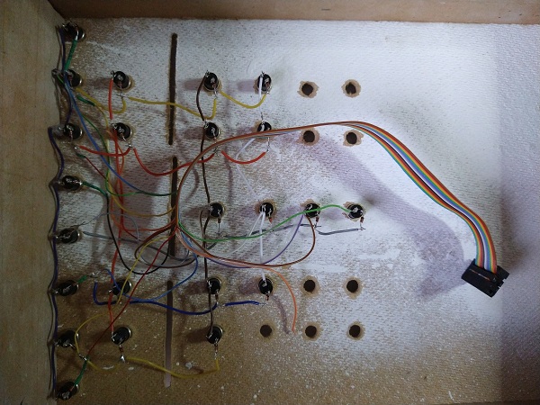
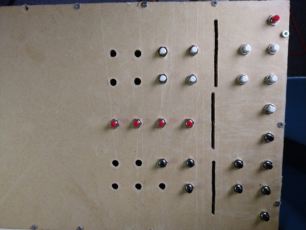
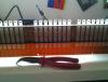
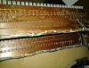
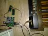
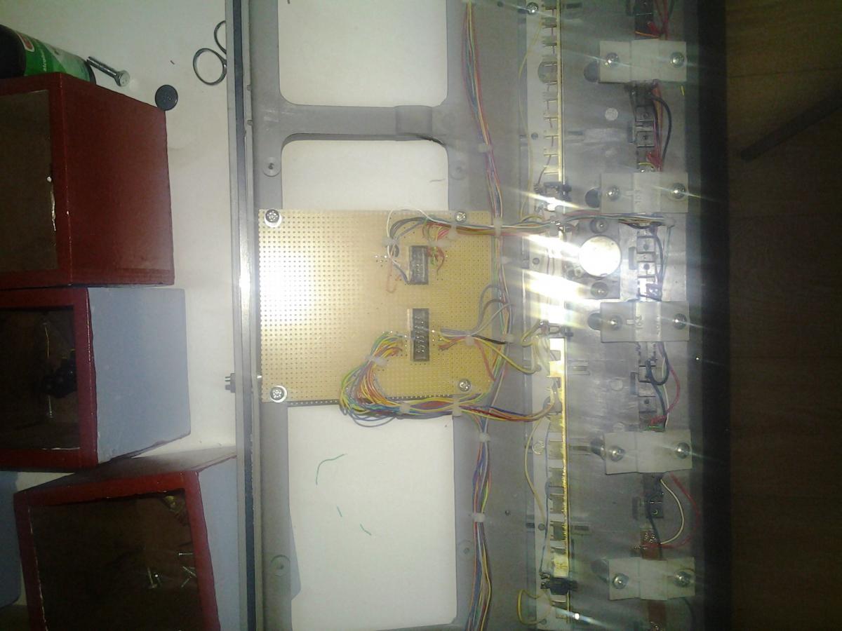
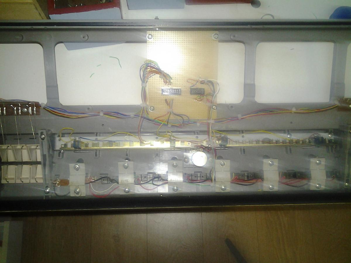
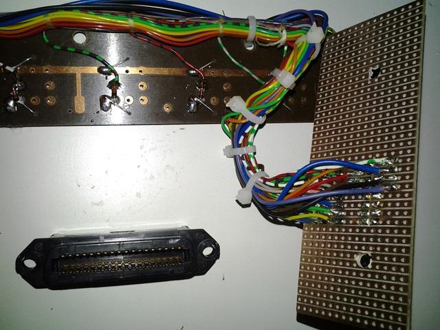
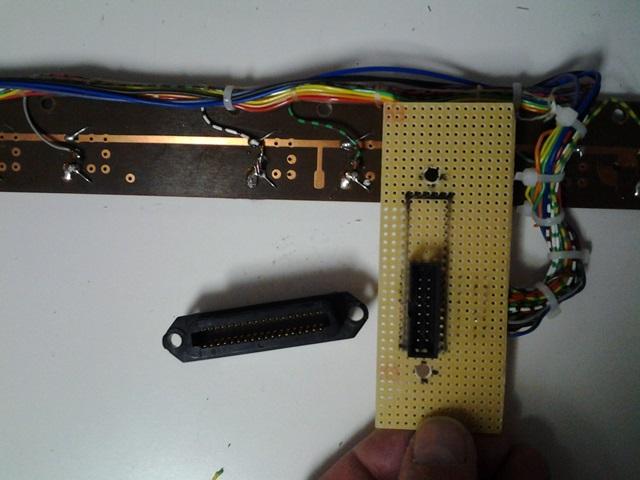
My English is not very good. I am trying to build an electronic stop knobs board. If I press a knob I want a signal to my grandorgue program. Later on I want to connect leds to indicate the state of the button.
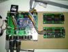
I made board, soldiered the button switch and connected them to a dio_matirix. The lpc17 had an old bootloader with midio128. I succeeded in installing midibox NG. The file "default.mio" was still on the SD card so I deleted it.
The stop knobs (buttons) are not working out of the box. All the column buttons send the same note.
I read a lot of manuals, but I do not get clear where to start. Probably edit the "default.ngc"....
Any help is appreciated.
Robert
-
hello Thorsten,
yes: currently you are using 0xB0 for each input, which means: send CC over MIDI channel #1In order to send over MIDI Channel #2, just change this to 0xB1
okay, got it.
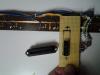
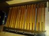
Please re-solder, it's more consistentI have done that. I was in doubt whether to wait for the new faders (the old faders are worn), but I re-soldered some and some others I placed some upside down (left / right turns that way). It works!
Scaling analog values isn't provided by the MIDIO128 applications.If this is required, go for MIDIbox NG!
(and btw.: MIDIbox NG allows you to swap min/max without re-soldering the pots)
MIDIO128 is a primitive application for beginners: you get what you read in the documentation. ;-)
MIDIbox NG is much more flexible, but also requires that you read more documentation...
I guess I am getting addicted to playing with midi-hardware stuff... I will try out the Midibox NG soon. First I am going to find out how Rosegarden, fluid-synthesizer work (some midi basics...) with the current config of the organ.
Robert
-
Hello,
I connected my brand new ainser module to the "mainboard" Midibox 128 v3 and did some testing: the jitter is 20.
I suppose I have to inform the Midibox about the connect Ainser module by editing the default.mio.
#AINSER;Pin;USB1;USB2;USB3;USB4;IN1;IN2;IN3;IN4;RES1;RES2;RES3;RES4;OSC1;OSC2;OSC3;OSC4;Evnt0;Evnt1
AINSER;0;1;0;0;0;1;0;0;0;0;0;0;0;1;0;0;0;0xB0;0x10
AINSER;1;1;0;0;0;1;0;0;0;0;0;0;0;1;0;0;0;0xB0;0x11
AINSER;2;1;0;0;0;1;0;0;0;0;0;0;0;1;0;0;0;0xB0;0x12
AINSER;3;1;0;0;0;1;0;0;0;0;0;0;0;1;0;0;0;0xB0;0x13
AINSER;4;1;0;0;0;1;0;0;0;0;0;0;0;1;0;0;0;0xB0;0x14
AINSER;5;1;0;0;0;1;0;0;0;0;0;0;0;1;0;0;0;0xB0;0x15
AINSER;6;1;0;0;0;1;0;0;0;0;0;0;0;1;0;0;0;0xB0;0x16
AINSER;7;1;0;0;0;1;0;0;0;0;0;0;0;1;0;0;0;0xB0;0x17
AINSER;8;1;0;0;0;1;0;0;0;0;0;0;0;1;0;0;0;0xB0;0x18
AINSER;9;1;0;0;0;1;0;0;0;0;0;0;0;1;0;0;0;0xB0;0x19Is that right? And how?
The ainser64 faders are on channel 1 by default: can I change this?
The volume goes in the opposite way: low volume is high and vice versa. Shall I "re-soldier" the 5V and 0V of the faders or is there a software solution?
Is there a way to define e.g. 1200 = minimum volume and 3500 = maximum volume?
Maybe I missed a documentation, but I cannot find it...
Can I plug the pistons in the Diomatrix module? I know how to change the channel, but should I edit some more things in de default.mio or should I edit the pc software (eg pc organ / jorgan etc.)
nice regards,
Robert

-
Thanks Thorsten: problem solved!
-
I connected both the pedals and the keyboard to my midio128. After some tuning (notes not working, broken ic etc.): all notes work and I can play. But sometimes I get some random ghost notes especially when I use the pedals. Even if these ghost notes sound funny: there are difficult to stop... So I want to get rid of the ghost notes. Possible solutions I could think of:
1) reduce the length of the wires: hardly impossible
2) replace the reedcontacts of the pedals (22 out of 27 are very old)
3) connect a powersupply to the diomatrix of the pedals
4) reduce the resistors of 10k to 100k?????
combination of the solutions...
Next step is to connect a swell pedal(s), fader and the registers. I ordered an ainser64 pcb so as soon as it arrives I will continu.
Robert

-
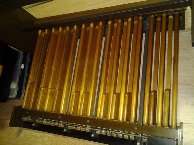
finished part one: pedals work properly!
-
Thanks Thorsten: succeeded in getting the right notes!
I am now going to finish the connections to the pedals.
Robert
-
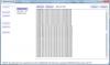
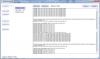
Thanks for the help. I edited default.mio, but I received an error while saving: applition expected... contact TK (see attachment for details).
kinds regards,
Robert
-
it is more complicated than I thought.
I cannot find any *.ini files or configuration files on my computer. I installed the bootloader and I uploaded the projec.hex (midio128_v3_016\MBHP_CORE_LPC17\project.hex).
So next step for me is:
1) I have to create a midio128.ini file? but I cannot find an example and have no clue what to put in it...
2) Open a shell and change to the directory which contains the midi128.ini file. Start the mk_syx.pl script with perl mk_syx.pl [ini-file] ?
Apart from the fact that it is a good idea to put the two matrices on a different channel: are you sure it is okay that all sr pins result in the same notes?
for example I expect sr2/d0 results in a notenumber 58 (A3) and not in a notenumber 49 (C#2).
Robert
-
Thanks for your reply. I will try to figure it out.
Robert
-
Hello,
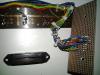
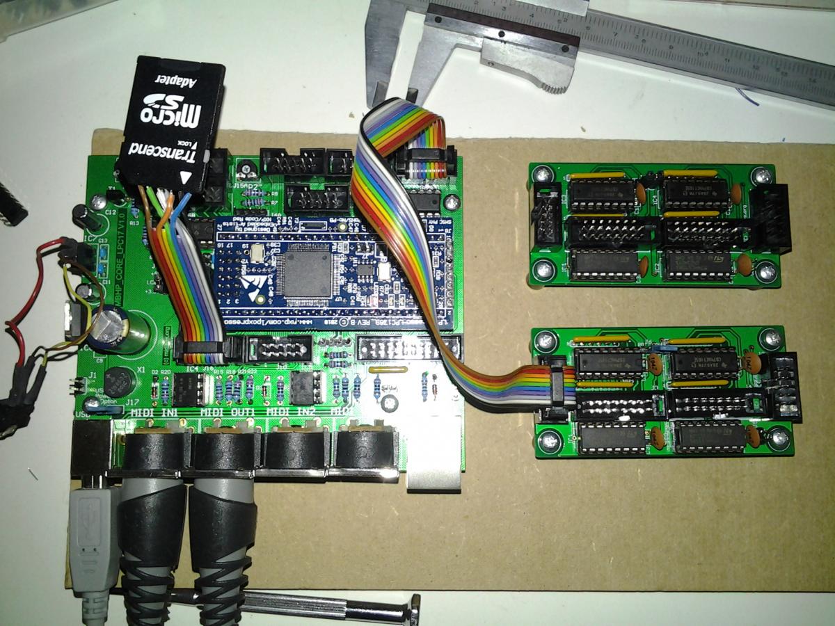
I am a newbee with few soldiering capabilities and few experience in programming. I want to midify an old organ. I started with trying to get the pedals to work.
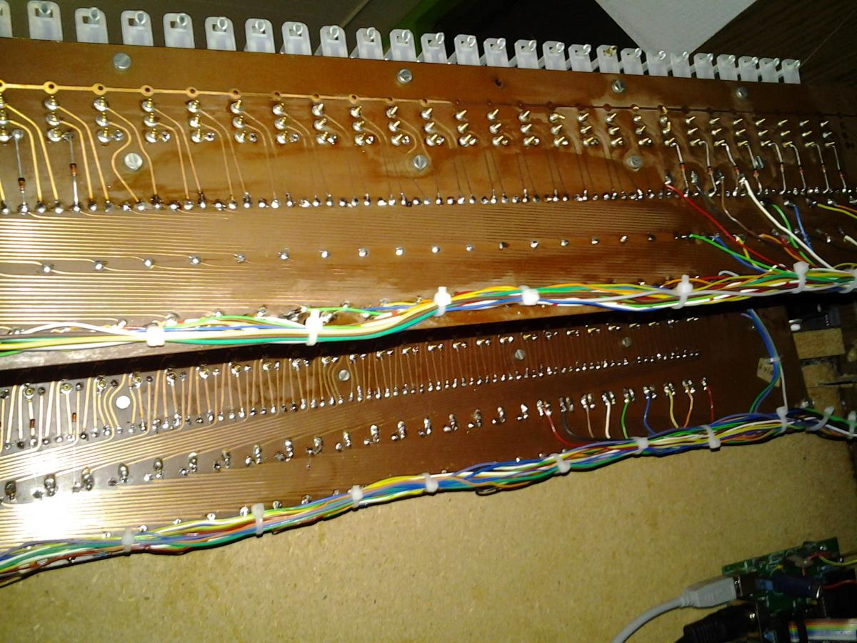
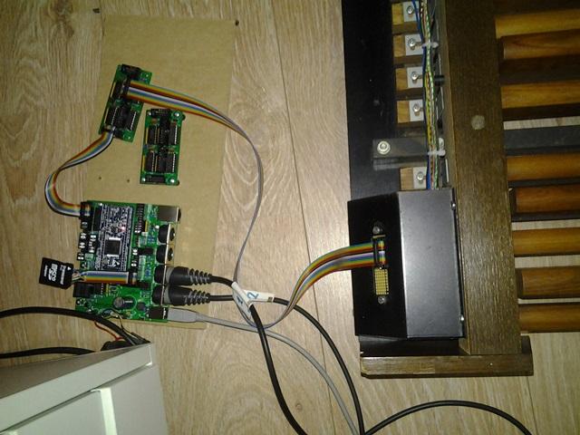
I soldiered a LPC17, put a lpcxpresso on it, connected SD card, connected a dio matrix. Upload mios bootloader and installed mios.
The problem: when I connect pin sr1 to d1 I get a C2 as expected. When I connect sr1 to d2 a C#2 and so on ... sr1 to d16 => D3. But I get the same notes if I connect pin sr2 to d1 (C2) or s6 to d1. So it makes no difference what ever sr pin I use: I receive the same notes.
I guess my dio matrix hardware is okay (capacitors too??), maybe some soldiering errors on the lpc17? software?
can someone give me a clue how to search for errors?
Robert


Stop knobs board
in MIDIbox NG
Posted
@totoraymond: Well you may not be an expert, but you are a genius!! I made the changes you proposed. After removing the other id entries it worked. Thank you so much!